
This page is a diary about the 20 foot diameter wind turbine we built over the winter of 2006, and the 75' tower we built to put it on. A couple of years ago we built a good 17' diameter wind turbine which has served us well. Between that machine and my PV Solar I really didn't need the power from a 20' machine. Mostly we built this for fun - and... I felt I needed a better tower. The tower under my 17' machine is pretty light duty for the machine on it and I don't expect it'll last long. It should do well with a smaller machine on it though.
As with most of the projects on this site, there is quite a bit of detail to follow but I did not include everything. You can probably get a fuller picture of the whole process by looking over smaller machines we've made, they are very similar in their construction. These pages are not plans! I cannot even say at this time if it's a decent machine or not - we did our best for what it's worth. It takes a lot of testing and time to determine if a wind turbine project is good - or now. It was lots of fun though and at the time of writing this it's been doing a nice job for a couple of weeks.
The machine is a dual rotor machine, much like the others we build. The design is very inspired by Hugh Piggott's ideas and much of the stuff we learned by attending his workshops. Lots of good ideas also come from the many folks on our discussion forum. We post almost every step of a project like this on our discussion forum and often times good ideas come up - it's been very helpful. Also a lot of good ideas came from friends and neighbors who come by to watch/help. I should think more than a few disasters have been avoided by having several minds going over each step along the way.

Pictured above is the wheel hub/spindle we used. It's got 6 holes on a 5.5" diameter. It's a trailer hub for a 6000 pound axle. As usual, whenever I finish a project like this I look back and wish I'd made things stronger. I could've easily fit a much larger hub/bearing assembly in this machine and to do it over again I would. That said - this hub is twice as strong as the one I used for the 17' machine and that one's been fine so far so I don't expect problems any time soon.

The machine has two magnet rotors. They're 22" in diameter and 1/2" thick. I had them water jet cut with 'spokes' in the middle. I think that looks neat and may aid in cooling the stator. Pictured above George is tapping out the 6 holes for the 'jacking screws' which we'll need to use for assembling/disassembling the alternator once the magnets are on.

I also had the template for placing the magnets water jet cut. It cost about $35 to have this cut out of 1/8" thick Aluminum with the CNC water jet cutter - money well spent when you consider the time involved in making this from wood and consider the fact that you'd never get it perfect.

Sorry for the blurry picture, its the only one I have. In it we have a few magnets stuck down. This machine has 20 magnets per rotor. They are the same magnets we used for the older 17' machine (it had 16 per rotor), they are 1.5" wide, 3" long, and 3/4" thick. The cost of the magnets on this machine was about half the cost of the machine overall. It's interesting to think about blade diameter and alternator cost. Whenever we double blade diameter, we generate 4x the power and half the speed. So we need approximately 8x the alternator overall with a 20' blade as we do with a 10' blade it seems. The 10' machines we make have 24 cubic inches of magnetic material in them. This one has 135 cubic inches of magnetic material in it. The 10' machines have about 6 pounds of copper in them - this has close to 30. The 10' machines weigh about 70 pounds without their blades. This 20' machine came in right at 400.

The two rotors have all the magnets glued down with cyanocrylate glue and they have a nice safe place to hang. These magnets are extremely powerful and the completed disks are very dangerous. I have no doubt they'd crush every bone in your hand if they came together on it - they need to be treated with extreme caution.

We put a center island in the middle of the magnet rotors made from plywood, and dammed up the outer diameter with electrical tape. We mixed West system epoxy with chopped fiberglass strands and poured it about 3/8" thick. The epoxy does a much better job of adhering and not breaking/warping in the magnet rotors than does the polyester we used to use. The polyester sometimes shrinks badly too - and the epoxy doesn't seem to.

There's a magnet rotor all finished up.

Pictured above we've bolted the back magnet rotor to the front of the wheel hub. The studs are 12" long, cut from 5/8 - 11 allthread.

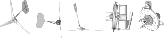
Here we're starting to assemble the alternator head. I had a few parts for this machine cutout in town with a CNC water jet machine. It costs more but you get perfect parts. The stator on this wind turbine is 28" in diameter - the stator bracket has 5 'fingers' and it's 28" in diameter. It's cut from 3/8" thick steel. In the picture, the wheel spindle is pointing down, clamped in a 3 jaw chuck and we're preparing to weld it to the stator bracket.

The spindle is welded into the stator bracket and suspended in the back by a steel ring with a hole that fits around it. All that is held together with a 6" long piece of 6" sched 40 steel pipe.

There is the same assemble turned over with 1 bearing on the spindle. We left it like this for quite a while and test assembled the alternator on here - because it sits nicely on a workbench. Once the rest of the chassis gets welded together the machine gets too large and heavy to handle. I'm doing this page a bit out of order though and we'll stick with the rest of the steel assembly for now.

Here we've got both magnet rotors assembed on the hub and on the spindle. We had to use jacking screws to very carefully/slowly lower the top rotor on. The force trying to pull these together is incredible. We set it up with an airgap (Distance between the magnet rotors) of about .85". The next step is to figure out the coils. We'll come up with an appropriate shape/size of coil, and then wind a test coil and poke it between the magnet rotors. We'll spin the alternator at a known speed and by looking at the voltage of the test coil, the wire gage we wound it with, the number of windings in it and the rpm, we can determine exactly how many windings we need to get the alternator to start charging at the right speed. In this case, being a 20' diameter machine - our target is about 48 Volts at 65 rpm. We'll get into that on the next page.