Part 2
by Dan Fink
This article was orginally published in the August 2005 issue of the Energy Self Sufficiency Newsletter. DanF writes a monthly wind power column for the ESSN, and we at Otherpower.com highly recommended this publication for anyone interested in renewable energy. The ESSN focuses on homebrew and do-it-yourself projects instead of the expensive turnkey installations seen in many other magazines. Best of all, it's free! You can download both the current issue and back issues HERE.
In the first part of this series of articles, I covered how to Variable pitch blades calculate the power available in the wind and its relationship The most elegant, efficient and effective way to regulate into turbine swept area and wind speed, plus other mechanical coming power, and also the most expensive and complicated and electrical efficiency losses in a wind turbine. These losses to build. give a realistic maximum Coefficient of power (Cp, or efficiency) of 35% of the power available in the wind for a small turbine. This crucial formula is: 
SURVIVING HIGH WINDS
All wind turbines must have a way to deal with this massive increase in available power as the wind speed goes up. In Part 1 of this series (see ESSN July 2005), we discussed the distribution of wind speeds, and how most wind comes to us at lower speeds. So, manufacturers try for the best performance between 7 and 30 mph, and design the turbine to simply “survive” winds higher than that while still producing near peak power. If the turbine was allowed to keep making power over 30 mph, it would – but only to the maximum power production rating of it’s generator or alternator, which can’t harvest much more power beyond that rating— so the huge amount of extra power in the wind will cause overheating, overspeeding, and possibly burn out the generator or cause the turbine to shed a blade.
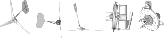
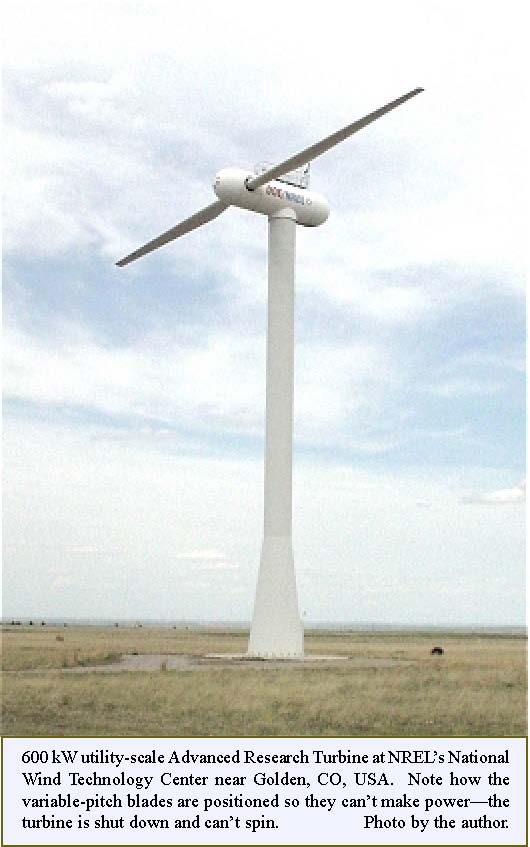
One very effective way to regulate incoming power is variable pitch blades. The blades can rotate in the hub and change the angle at which they hit the wind. All large utility-scale turbines use this method, regulated by sensors and active controls. Only a few small turbines use variable pitch blades, notably the Jacobs . Jacobs has been building the system since the 1920s, and you , can still buy one new! The system is not high-tech, but is
extremely effective—the blade pitch changes mechanically
Continued on next page
August, 2005 ![]() Page 18
Page 18
using a flyball governor and centrifugal force. In low winds, the blade pitch is very steep, and at peak output the blade pitch is very flat—this matches the blade’s angle of attack to the apparent wind (more on apparent wind later). If winds increase more, the blades pitch past flat, causing aerodynamic stall to prevent overspeeding.
Furling tail
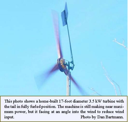
This is the most common high wind regulation technique in small wind turbines. The turbine frame is designed with a built-in offset, and the tail or the generator head is hinged both upwards and inwards. When windspeed starts to approach the generator’s maximum power output capacity, the tail or head folds up, yawing the machine at an angle to the wind.This reduces the effective swept area and thus the available power to the maximum power output level of the generator, so it continues to make peak power while furled. When wind speed drops, the tail or head drops back into a normal configuration via gravity and tracks the wind straight on once again.
Twisting blades
Some very small wind turbines use flexible plastic blades that bend, twist and flutter when power input gets too high for the generator to handle. This technique is effective, but also noisy. Some of the extra power in the wind is being turned directly into noise, and the sound of blades fluttering at high speed is very distinctive. It’s only used on very small turbines, and is effective only using modern plastic blades that are highly resistant to fatigue.
Mechanical and air brakes
These regulation techniques are no longer used in commercial turbines because they are very noisy and prone to mechanical failure from fatigue, rust, and ice. Nevertheless, I have to admit it’s exciting watching and hearing a 1930s vintage Wincharger deploy its air brakes during a gale!
Emergency shutdown
All wind turbines should have some mechanical or electrical way to shut them down (stop the blades from spinning) during severe weather events. These can including shorting the alternator phases, a crank that turns the tail into fully-furled position, or a mechanical brake. There’s no sense in abusing your expensive turbine and tower by letting the machine run during a hurricane, severe thunderstorm, or tornado, since the machine will make no more power in 100 mph winds than it will in 30 mph winds if it is furling properly.
Unless you are working with a tiny ‘science fair project’ windmill that’s capturing wind from an electric fan, some sort of regulation is needed or bits will fall off! Beware of any wind turbine whose builder claims that it doesn’t need to furl because it is built so sturdily (tested to 100+mph!). But how many times and for how long can it withstand such abuse? Also beware if the builder advises you to lower the turbine to the ground if high winds are forecast—it probably lacks a shutdown system.
WIND TURBINE TYPES
If you are considering buying or building a wind turbine for making electricity, you’ll almost certainly be comparison shopping for a modern, electricity producing, lift-based horizontal axis machine. But by taking a look at some historical wind turbine designs, it gets easier to explain the physics concepts involved.
Drag vs. Lift
Wind turbines are divided into two types, drag machines and lift machines, based on the aerodynamic principles they utilize, and two more types - Horizontal Axis and Vertical Axis machines - depending on their physical configuration.
Designs that use drag to make them spin are the oldest way to harvest wind power, and the easiest to understand. The blades or cups push against the wind, and the wind pushes against the blades. The resulting rotation is very slow. And the blades or cups that are swinging back around after making power are hurting power output because they are moving
August, 2005 ![]() Page 19
Page 19
in the wrong direction, against the wind. The earliest examples of drag-based wind power design are grain grinding and water pumping machines from Persia and China, with records dating back to 500-1500 AD.
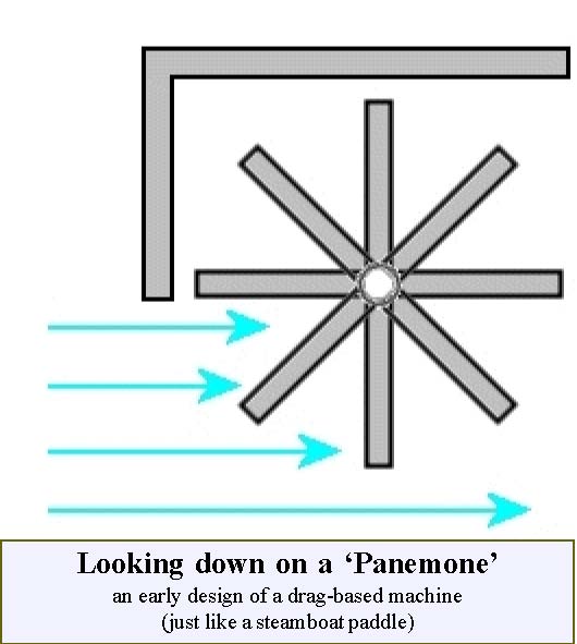
Note the wall that’s erected around the half of the machine that is hurting performance by moving against the wind. In any drag-based design, the blades can never move faster than the wind. This turns out to be a critical concept for both efficiency and the ease of generating electrical power.
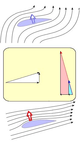
Lift-based wind turbines are the standard now, but lift concepts have been in use for thousands of years. Mariners as early as 3200 BC used lift whenever they took a boat with sails out onto the water and turned the sails to give the boat maximum speed. An airfoil shape (just like the cross section of an airplane wing) gives lift, and has a curved surface on top. Air moves over the curved top of the airfoil faster than it does under the flat side on the bottom, which makes a lower pressure area on top, and therefore an upward force—that’s lift. The key concept of lift and wind power is that lift forces allow the blade tips of a wind turbine to move faster than the wind is moving.
HORIZONTAL AXIS WIND TURBINES (HAWTs)
and VERTICAL AXIS WIND TURBINES(VAWTs)
HAWTs are what most people first think of when someone says “windmill” — blades moving perpendicular to the ground.
In a VAWT, the blades move parallel to the ground. Both HAWTs and VAWTs can be either drag or lift based, though only lift designs are commonly used as they are reasonably efficient for electricity generation. Below are some commonly seen wind power designs, and explanations of the principles on which they work.
“Dutch” HAWTs
While not exclusively Dutch in origin, these machines were built all over Europe for grinding grain, and the earliest ones were drag-based.
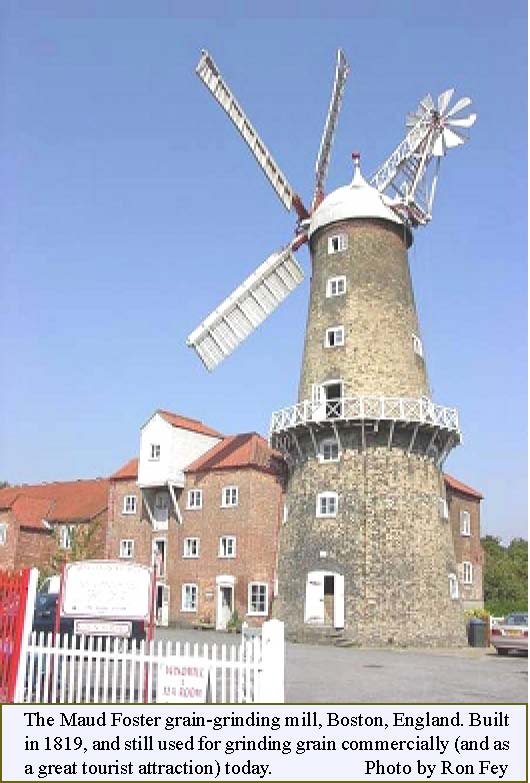
The Dutch made major improvements circa 1390 AD by incorporating lift into the blade design. The machine was pointed into the wind manually by the operator.
August, 2005 ![]() Page 20
Page 20
American Waterpumping HAWTs
Over 6 million of these were installed on farms and ranches across America, starting in the mid 1800s.
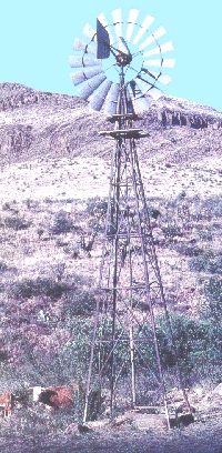
A typical Aermotor water pumping windmill, still common and in operation all over the American West. Photo courtesy of DeanBennett.com, Denver, CO. This company sells all the replacement parts to keep these beautiful old machines running, and also sells new waterpumping windmills.
They were used purely for mechanical power to drive a pump shaft in a well, and point into the wind via a tail vane. Many of these antiques are still in use, and some are still manufactured new! Companies like Dean Bennett in Denver, CO, USA still sell all the replacement parts to restore and maintain waterpumper mills, and also sell brand new machines. These designs are mostly drag-based, providing high torque for the pump shaft, but low blade speed. This makes them difficult to use for electricity production, but excellent for moving that heavy pump shaft.
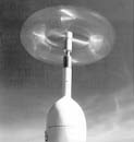
Modern Electricity-Generating HAWTs: They come in sizes ranging from tiny (4 foot diameter, to mount on a sailboat or remote cabin) to huge (300 foot diameter, multi-megaWatt, utility-scale machines). These machines can be designed for either ‘upwind’ or ‘downwind’ operation. In upwind turbines, the blades are in front of the tower toward the oncoming wind, and point into the wind using a tail vane or (in giant turbines) electronic controls. Downwind turbines don’t have a vane, and the blades are behind the tower relative to the wind. While upwind designs are the most common, there are excellent downwind machines commercially available.
All modern electricity-producing HAWTs are lift-based, so the blade tips can travel faster than the wind.
The resulting high RPMs are ideal for producing electricity, and these machines can be highly efficient. Small machines are approaching 35% efficiency (Cp=35%), while utility-scale machines are rapidly approaching the Betz Limit (Cp<59.26%, see Part 1 of this series, ESSN July 2005).
Drag-based VAWTs
The ancient Persian design shown before, the Panemone, is one example. Other designs include the Savonious Rotor which can be easily built using coffee cans, plastic buckets, or metal barrels.
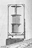
Savonius
Photos courtesy the American Wind Energy Association AWEA
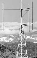
Anemometer
A simple anemometer is another drag-based VAWT design. While fun for experimenters and students to build and test, these designs are extremely inefficient, and give only low torque since the blades or cups can never travel faster than the wind. Yes, I know ... anemometers often spin quite fast, but as they usually have a very small arm length, they have very little torque.
August, 2005 ![]() Page 21
Page 21
Lift-based VAWTs
Darrieus, Giromill, and H-rotor designs are big improvements over drag-based machines, since the blades have airfoils and utilize lift to move faster than the wind. However, there are inherent difficulties with any VAWT design, and these problems are why VAWTs have never been very successful in the commercial market, on either small or large scales.
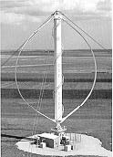 Photos courtesy the American Wind Energy Association AWEA
Darrieus
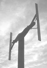
Giromill
H-rotor
Should I choose a HAWT or a VAWT for my installation?
If you are looking for a fun wind power experiment or science fair project, a VAWT might suffice. You can find some good ideas here.
If you really need to make some serious electricity to power an on- or off-grid home, a lift-based HAWT is the best choice. Plus, you’ll have a very hard time even finding a commercial VAWT from a reputable manufacturer for sale in any size.
The disadvantages of VAWTs are numerous:
VAWTs must be built at least twice as big as HAWTs to make the same amount of power, since half of the machine is moving in the wrong direction (towards the oncoming wind) at any given time (remember the Panemone?)
Because of this, VAWTs go through a fatigue cycle on every rotation. This means the design must be very strong and sturdy—which also translates to higher cost and more weight.
More weight also mean that the tower must be more sturdy, another added expense. All wind turbines must be flown high in the air to get above obstructions. Near the ground, on a rooftop, or in any direction from obstructions such as buildings, slopes, or trees, turbulence steals large amounts of power and causes unnecessary fatigue in both HAWTs and VAWTs.
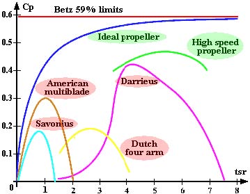
In general, VAWTs are also lower in efficiency than HAWTs. Drag-based designs of any kind are the worst because maximum possible efficiency (Cp) is directly related to how much faster than the wind the blade tips are moving. This ratio of blade speed to wind speed is called the Tip Speed Ratio (TSR), and the best possible Cp is obtained around TSR = 5-6. Only lift-based VAWT designs can even approach this TSR, and are still limited by the other factors listed above.
VAWT
HAWT
This diagram shows the maximum Cp theoretically possible, versus Tip Speed Ratio, for different wind turbine designs. Courtesy of http://www.windturbine-analysis.com/ (Note: used without permission - email address on website no longer valid)
WIND TURBINE BLADEAND ROTOR DESIGN
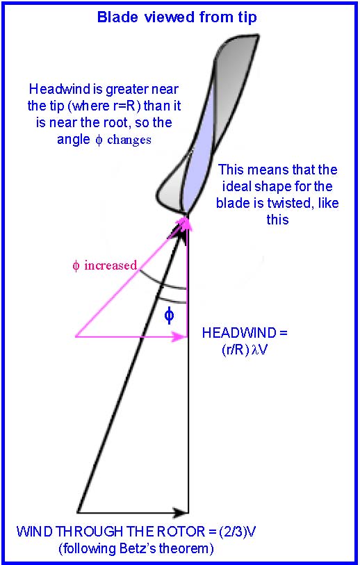
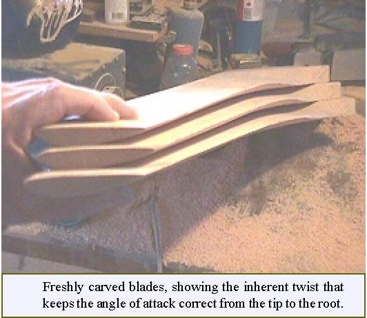
Many people are surprised the first time they look at wind turbine blades and rotors close up. The flat sides of the blades face the wind, and they have a distinctive twist to them, from a steep pitch at the root to a very shallow pitch at the tip. Why is this, and why do some turbines have more blades than others?
With HAWTs, the blades are inclined to the oncoming wind and constrained to move around a horizontal axis of rotation. They start to move by deflecting the wind, just like a rudder inclined to the flow of water forces a boat to change direction. However, like an aircraft wing, their airfoil cross section adds lift to the blades as they speed up, and greatly increases the rotational force. The blades are wide at their base and taper as they go out because the tips move faster
Continued on next page
August, 2005 ![]() Page 22
Page 22
than the base. They are also twisted so that the angle off BLADE TWIST attack decreases from where the air is moving relatively slowly
August, 2005 ![]() Page 23
Page 23
When the angle of attack is wrong for the apparent wind, the airfoil stalls and ceases to produce lift—the same thing that happens when an airplane tries to climb too steeply for its speed and begins to fall. When a wind turbine rotor begins to start spinning from a full stop, it is always stalling. As the wind increases and the blades pick up speed, the angle of attack gets better and better, and the turbine accelerates dramatically from the added lift force. It’s fun to watch this happen! And a turbine can stall at higher windspeeds too—it will no longer pick up RPMs as the wind increases. This is not frequently observed, as the turbine has usually furled by that point to reduce wind input.
As the number of blades and the amount of the swept area that’s taken up with their surface area increase (this ratio of blade surface area to swept area is called “solidity”), more torque and less RPM are produced, the tip speed ratio is lower, and the blades must be proportionally narrower. The typical 3-bladed rotor is the best compromise for physical strength and rotation speed.
MORE MYTHS
Now for some more myths, as promised in part one of this series. There are many myths going around about wind turbines, especially VAWTs. Unfortunately for VAWT enthusiasts (some of whom are probably already drafting irate emails to me), almost every wind turbine investment scam (ranging from small scale to utility scale) in the last 50 years involved VAWTs. The reason for this abundance of scams is simply that VAWTs look new and different, and are intriguing to the public. Some examples (fictional, but similar to actual advertising claims):
Invest now in this unobtrusive, world-changing, previously suppressed, new technology that will put a (insert company name) wind turbine on every rooftop in America, solving our energy crisis and oil shortage problems!
First of all, VAWTs are not new technology—see the ancient Persian Panemone VAWT pictured before. The technology has not been suppressed—The US Government NREL, DOE and Sandia laboratories have extensive tested and computer modelled VAWT performance. Furthermore, rooftop installations are not practical—turbulence affects both HAWTs and VAWTs, and they must fly in smooth air, well above any obstructions. Now take the average energy usage for an average home – about 9000 kW/h per year in the US, and 5000 kW/h per year in Europe. Take the yearly power production estimates from a reputable wind turbine manufacturer at a reasonable average wind speed (say 5 m/s, 11 mph). For a Bergey XL.1 (8.2 foot diameter rotor), Bergey estimates 1800 kW/h per year. So you’d need 5 of these flying on tall towers and above all obstructions to possibly power your 9000 kW/h per year house. Now remember that VAWTs must be twice as large as HAWTs to make the same power. The 5 Bergeys would sweep 284 square feet. The VAWT would have to sweep 567 square feet to get the same power output—that means a machine at least 24 feet high by 24 feet wide, mounted at least 20 feet above the nearest tree or building. That doesn’t sound either practical or unobtrusive. Hold on tightly to your wallet, and consult an investment counsellor before spending money.
Wind turbines with only 2 or 3 blades let too much wind slip through and be wasted—my Savonious VAWT (or multi-blade waterpumper-type) design will capture ALL the wind.
This is a myth! The Betz limit of Cp<59.26% applies to both HAWTs and VAWTs. Behind and in front of every operating wind turbine the air is moving slower, and the wind tends to go around the machine instead of through it. Plus, both the Savonious and American Multiblade designs are mostly drag machines, and therefore very limited in efficiency because of their low Tip Speed Ratio (see chart on previous page). Modern utility-scale wind turbines are coming close to the Betz limit, but drag designs have little chance of ever coming near even half of it.
More blades means you get more power! Replace your existing 3-blade rotor with our 6/8/12/16 bladed rotor and outperform all 3-blade designs.
Not a good idea, you’ll actually get less power from your existing machine! Wind turbine alternators and generators are designed to work in a specific RPM range, and lowering their RPM and TSR by adding more blades means you get less power, not more. The torque will increase, but that doesn’t help your electrical generation at all. For the same reason, it’s not practical to convert an American Multiblade Waterpumper windmill to make electricity—the RPMs are much too low, and adding any kind of gearing to increase shaft speed seriously hurts power output, especially in (the most common and most important) low wind speeds. 3 blades are the best compromise of RPM vs. torque. Any design with high solidity won’t be suitable for producing electricity efficiently.
In conclusion: we’ve made it through most of the wind power math now (heave a sigh of relief!). Forthcoming articles on this subject will be USDA-certified math-free, and cover wind turbine siting, towers, electrical regulation and dump loads, off-grid vs. grid-tied systems, and resources for choosing a commercial or home-built wind turbine design.
Dan Fink