Homebrew 10 foot Wind Turbine, ALTERNATOR ASSEMBLY
This page details how we assemble our alternator from all the finished parts. At this point we've completed all the metal work and it's been painted. The magnet rotors and the stator are finished, and we're finally assembling the machine.
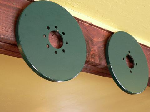
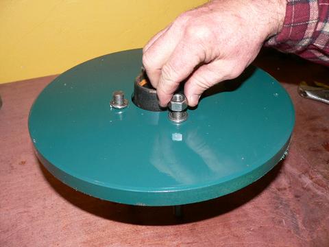
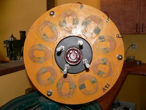
Pictured above are the finished magnet rotors. They are identical, except that the front rotor (closest on the left in the picture) has 8 holes, 4 for the studs, and 4 for jacking screws which will allow us to lower it safely and raise it back off the alternator if necessary. Each rotor also has a small mark (a divet made with a drill bit) so that we can align the two rotors properly.
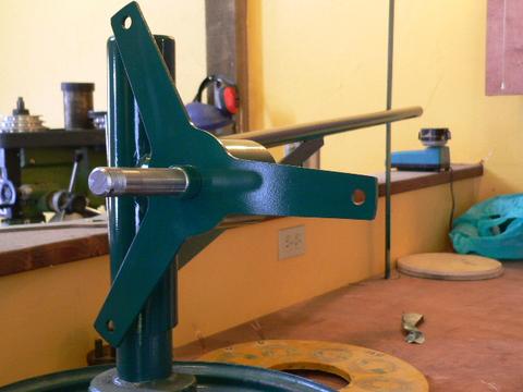
Here is the main chassis for the machine all painted and ready for assembly. It's handy to have a stand so we can turn it around/position it for easy assembly.
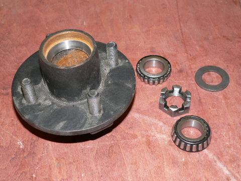
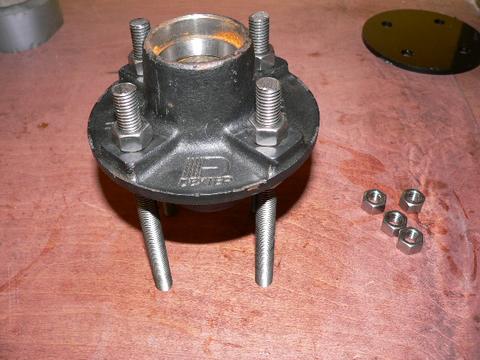
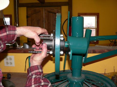
Pictured above is the wheel hub, bearings, washer and nut. Not pictured is the cotter pin. Typically when we order the hub, we get the bearings. The washer, nut, and cotter pin comes with the spindle. The hub is Dexter part number 81- 9A, and the spindle is designed for this hub, but they are always sold seperately. Most trailer parts supply houses can provide this. I like the Dexter hub because it seems to be the most common one available, and it comes machined on both sides. Many hubs are machined only on one side which makes assembly more difficult. If a different sort of hub is used, I expect that the lengths of our allthread studs would change, and you may find the need to use extra shims to set the airgap between the magnet rotors properly. With this hub, things are very easy.
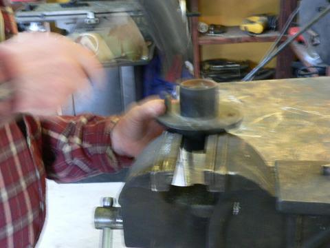
When delivered, the hub has 4 studs pressed into it (this is to accept the lug nuts that hold a trailer rim on). We need to knock those out with a hammer. It goes quite easily.
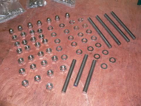
Pictured above is all the hardware required to assemble the machine except for the bolts/nuts that hold the tail on. I prefer to use all stainless hardware so that it can never rust, but this is optional except for the hardware that is near the edge of the magnet rotors that holds the stator. We will be relying on nuts and lock washers to act as 'spacers' between the magnet rotors, so it is important that we use fairly high grade hardware and make certain that all the nuts/washers that are used between the magnet rotors are the same height. I find that with cheap hardware this is not always the case, with stainless hardware it usually is. Here is a list of hardware:
- 1/2 - 13 nuts, qty 25
- 1/2 - 13 acorn nuts, qty 7 (we could use normal nuts instead - acorn nuts just look neat)
- 1/2 - 13 allthread 6.625" long, qty 4
- 1/2 - 13 allthread 4" long, qty 3
- 1/2" lock washers, qty 18
- 1/2" washer, qty 6 (I use the smaller AN style and they must be stainless. If we need to shim the airgap wider, we may require more than 6 of these)
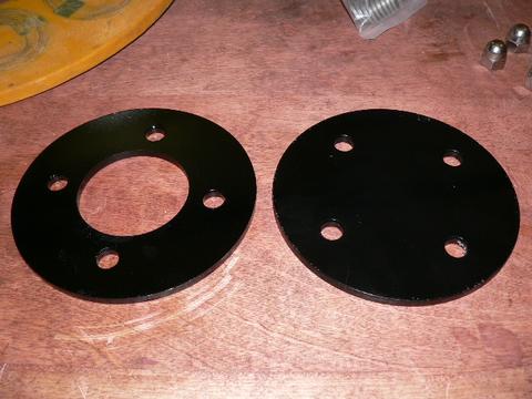
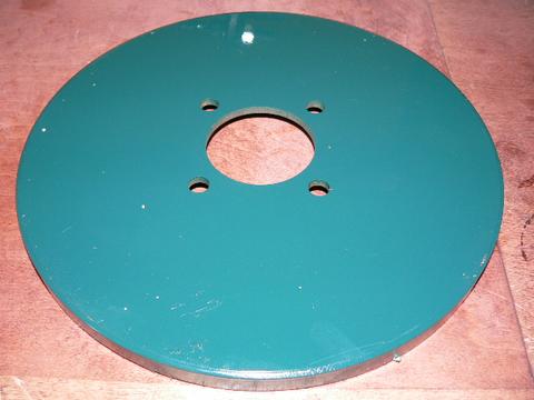
These are the steel hubs we 'sandwich' the blade betwen. They are 6" diameter with 4 holes on 4" diameter to fit our Dexter hub. The one with the hole (2.75") goes behind the blade, the other one goes in front of the blade. I show these now because they (one of them) come in handy when assembling our alternator. Otherwise we'll not use them till we install the blades.
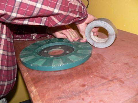
Before we assemble the alternator it's important that the magnet rotors be clean. Often times while building these we find that bits of metal/grindings get stuck to the magnets. They lay pretty flat on there, but when we assemble the alternator (put the two magnet rotors on facing each other) all the chips will stand up and rub on the stator. We need to clean it now. A good way to remove metal chips from the magnet rotors is with duct tape.
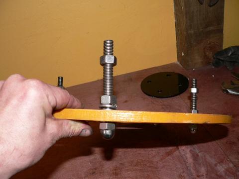
The first step is to take the 4 pieces of allthread which are 6.625" long and put one nut on. We screw the nut down on one end so that there is 7/8" of allthread behind it.
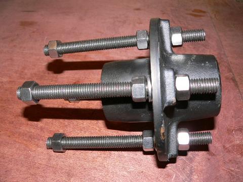
Then we put the long end of the allthread through the backside of the wheel hub. Put on a lock washer, and another nut and finger tighten the allthread to the hub (no need to get things tight here - just finger tight is what we want). Do this with all 4 studs, and then run a nut onto the front of each stud so that about 1/4" of allthread is protruding. So, if we look at one stud here starting at the front (left to right in the picture) here is whats important: 1/4" of allthread, 1 nut, more allthread, a nut, a lock washer, the wheel hub, a nut, and then 7/8" allthread.
We take the back magnet rotor (the one with only 4 holes) and turn it so that the magnets face down on the bench. (be sure the bench is clean from metal bits)
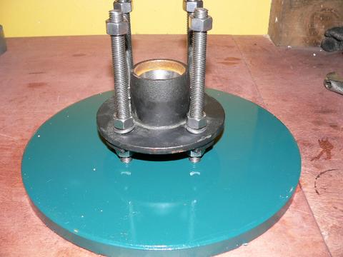
Take the back of the hub and put it into the hole in the magnet rotor, such that the ends of the studs (the ends that are 7/8" long) are poking into the 4 holes. We do this to align things before we tighten anything.
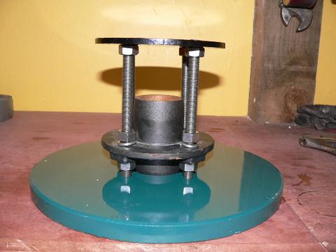
Then we use one of the steel blade hubs (the ones above that are painted black) and place it over the studs on the top and it should come to rest on the 4 nuts that we put up there. (thats why we put those nuts there with 1/4" of allthread sticking out). If we don't have these blade hubs, we could use the front magnet rotor, I would do it with the magnets facing up so that we can tighten things without worrying about magnets grabbing our wrenches. If we do it this way with something to align our studs both at the top, and the bottom - we are fairly assured that the studs are well aligned and everything will fit together nicely.
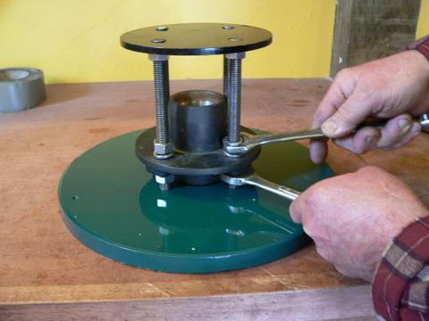
Now we can tighten the nuts on both sides of the wheel hub. We should get them very tight, and the goal is to move only the top nut (the one with the lock washer under it) and not the bottom one, so that we are sure to have 7/8" of allthread behind the back nut.
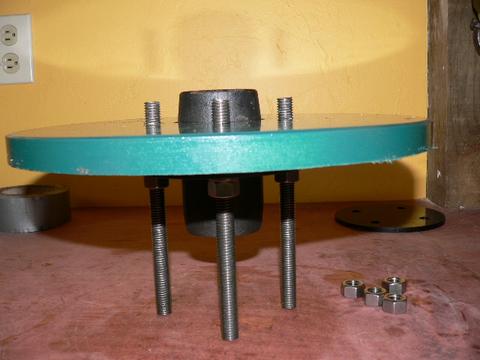
Then we can remove the hub from the top and the 4 nuts that held it there. We also remove the hub from the magnet rotor. Turn the hub upside down (so the back is facing up and we have 7/8" of allthread sticking up). If the studs were cut accurately and the nuts positioned properly, the hub should sit pretty flat on the ends of the studs as pictured.
Carefully lower the back magnet rotor down onto the hub so that the studs go through the holes. The magnets should be facing down. Remember the hub is steel and the magnets will attract it strongly. If you bring it down right on center its fine, but if things are off center the rotor will grab the hub. Sometimes it's handy to have someone holding the hub down and helping to keep things positioned.
On the back side of the magnet rotor each stud gets 1 lock washer and 1 nut. We can tighten these a bit with a wrech now, but it's easier to really tighten these ones after the alternator is together.
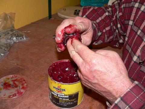
Now we can grease our bearings. Press lots of grease into both bearings, work the rollers around for a while and be sure the bearing is well greased.
The front and back bearings are identical for this wheel hub. Put one of the bearings on the wheel spindle and push it back all the way. It's probably a good time to mention... usually when you order a hub, it comes with a seal. We do not use the seal in a wind turbine, it creates too much friction and prevents easy startup. I believe if we grease the bearing well then they should be fine for quite a long time.
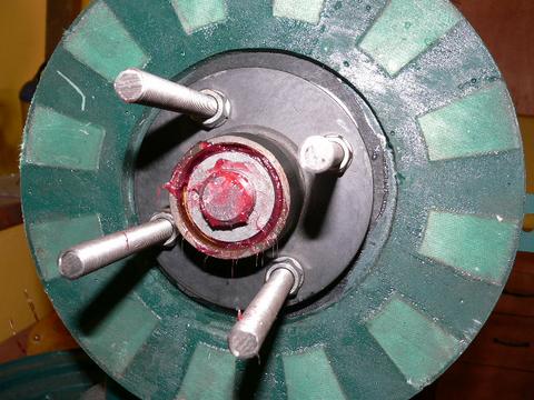
Carefully pick up the hub/back magnet rotor by the studs and place it onto the spindle, up against the back bearing.
Then insert the front bearing. Usually at this time I press a little more grease into the front of the bearing... can't hurt.
The place the washer in front of the bearing.
Then tighten the nut over the bearing. Get the nut reasonably tight, and then back it off so that you can insert the cotter pin. Once the cotter pin is in, I usually back the nut off as much as the cotter pin will permit. We don't want the nut tight, there should actually be a touch of play. You can feel how when the nut is tight, if you turn the hub it has a good bit more drag than when it's just slightly loose. If the nut is too tight, the machine will not startup easily and the bearing will die young. There needs to be a touch of play here. This is a good time to spin the hub and see that the magnet rotor runs reasonably true. Rotors cut from 1/4" steel are rarely perfectly flat, so we expect a bit of wobble and it won't hurt anything, but the less the better. If there's something seriosly wrong, now would be the time to catch it.
Next we'll mount the stator to the machine. Take the 3 pieces of allthread 4" long and screw an acorn nut down all the way on one end. Then put one of the stainless washers on.
Insert them through the 3 1/2" holes in the stator. On the back side of the stator we want another stainless washer, a lock washer, and another nut. We can finger tighen these - but we don't want them real tight yet. Then run 1 more nut down about 1".
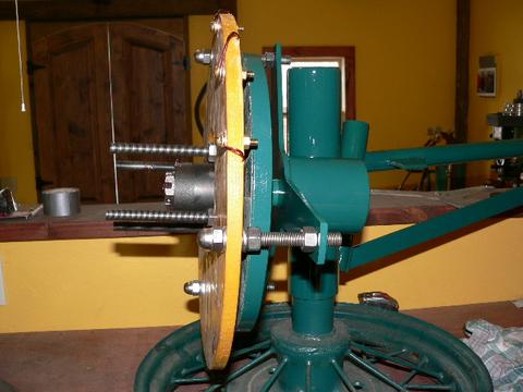
Then put the assembly onto the wind turbine, the 3 studs should fit through the 3 holes in the stator bracket. We can adjust the back nut (the one against the stator bracket) with our fingers and set an approximate airgap (say 1/8") between the stator and the magnet rotor now.
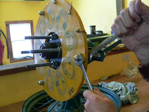
Now is the time to tighten the nuts on the stator. We should get these reasonably tight, but not so tight that we crack the resin. We won't touch these again - any further adjustments should be made at the stator bracket, not the stator.
On the studs where they come out through the back of the stator bracket, we put a lock washer, and a nut. Now, using two wrenches we can set the clearance between the stator and the back magnet rotor. About 3/32" is nice.
We also need to check and make sure that the stator is well centered around the wheel hub, we don't want it rubbing here. If it's not well centered - but our holes were drilled correctly in the stator then it's usually because either nuts are not tight yet, or perhaps the stator bracket is warped. If need be we could bend the stator brackets a bit. If it's not centered well it should be simple to find the problem and adjust for it somehow - but it's very important that the stator have good clearance here.
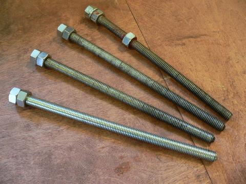
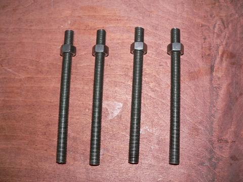
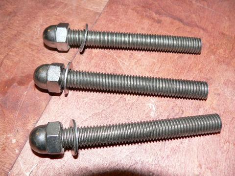
Pictured above are 4 Jacking screws (these were not shown or listed earliier with the hardware - these are tools, not part of the wind turbine). I like to cut them about 10" long, they are made from 1/2" -13 allthread. One end we double nut (jam two nuts together tightly) and the other end needs to have a slight chamfer ground on it. (this keeps them from getting 'mushroomed out' when they rub against the wheel hub) After we grind the end, we usually need to clean up the threads with a file. Test them by running a nut up on the end which was ground.
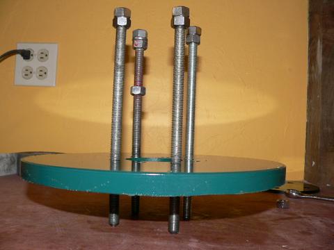
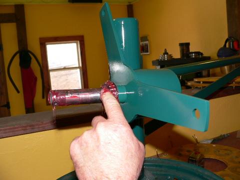
Run the jacking screws into the front rotor so that about 3" sticks out on the magnet side. Its nice to keep them very even (all of them poking out the same amount) or else things will bind up. Sometimes it's a good idea to run a tap into the threads for the jacking screws before we do this - if the paint makes them hard to turn, clean the threads with a tap. A bit of oil on the screws doesn't hurt either. It's nice when these turn easily by hand.
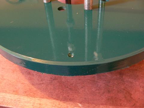
Take note of the divet - it's our alignment mark. I usually turn the back magnet rotor so that the alignment mark is poiting straight up (noon) and we'll put the front magnet rotor on the same way - so that it's alignment mark is also in the noon position.
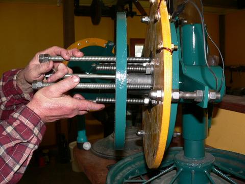
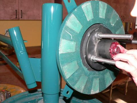
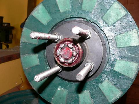
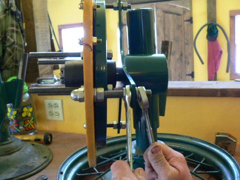
Carefully pickup the front magnet rotor by the jacking screws (do not get your figers near the magnets - jacking screws make a nice safe handle) and place it over the studs sticking out of the alternator. Push it onto the alternator and you'll feel the magnets 'grab' each other. It should pull down so the 4 jacking screws come to rest on the hub.

Then use a wrench and a bit of patience to lower the front rotor down. Keep the 4 jacking screws even. Usually it works best if we go around giving each jacking screw about 1 turn, and we go around the circle till the front rotor comes to rest on the 4 nuts which hold the studs to the wheel hub. This Dexter hub, and this arrangement of nuts/washers as spacers makes for about a perfect airgap if your stator is 1/2" thick. If the stator is thicker than 1/2", you may need to remove the front rotor and put washers behind it as shims. In most cases thats not necessary.
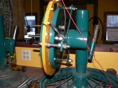
At this point our alternator is assembled. The clearance between the rotors and the stator should be around 3/32", 1/16" is probably acceptable in some places but any less and I'd shim things out. One both rotors are on, we can fine tune the position of the stator using the nuts on both sides of the stator bracket. At this point we can test the alternator. One easy test is to short each phase. When any single phase is shorted it should become stiff - but kind of lumpy to turn (it will cog). When all 3 phases are shorted together it should become very stiff, yet very smooth to turn. If we have a tachometer we can also test it with regard to volts/rpm. If we run the output through a rectifier and measure DC voltage, we should be hitting 'average' battery voltage at around 140 rpm.
Click Here to return to the front page of this project.