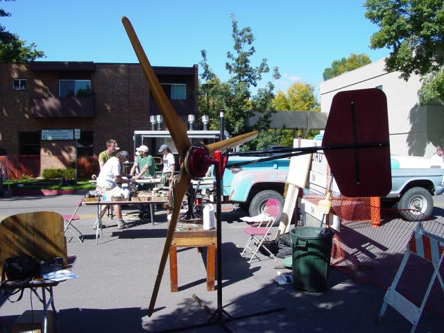
This page is a bit about a wind turbine we built with our freind and neighbor Tim, who wanted a 10' machine at his place. The machine was finished in Aug 2004 and we installed it in early Oct. Pictured above were displaying the machine at a workshop we gave at the Sustainable Living Fair in Fort Collins this summer in Sept.

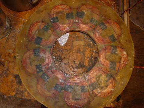
We built a lot of machines over the last year and a half. This is the 13th dual rotor machine along these lines to come out of my shop. The spindle is the bottom part of a strut assembly from a Volvo 740. Past machines have had larger 2" diameter magnets mounted on 11" brake rotors. Those alternators tended to be a bit too powerful for a 10' diameter prop, so this is the first machine I've made thats using smaller magnets (1" X 2" X 1/2" thick) and slightly larger 12" diameter rotors. These brake rotors come off the front of a Volvo S80. Pictured above we can see one of the magnet rotors with the magnets set in resin, mounted to the machine. On this machine, I only poured the resin up about half way to the tops of the magnets thinking that having the magnets poking out a bit would stir up some air and help cool the stator. In testing this alternator on the ground that definitely seems to be the case.
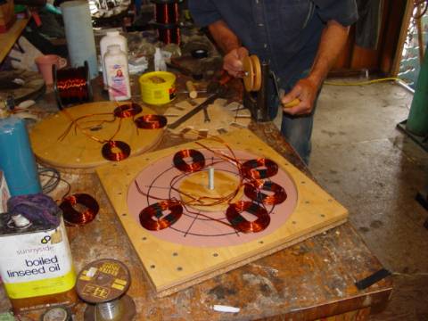
Pictured above Tim is winding up the coils. You can also see the new mould I made. This mould is 15" diameter, and the island in the middle is 5.5" diameter. This is a 12 Volt machine, and each coil is wound up with 34 windings of 2 strands of AWG 14 wire. This would be equivelant to 1 strand of #11 wire. #11 is a bit stiff and, in my opinion.. it's just about impossible to wind nice tight coils. These coils have to be wound neatly and tightly or they will not fit. I've used #12 for this too, and it works OK. I prefer to use two or more strands though when the coils call for heavy wire.
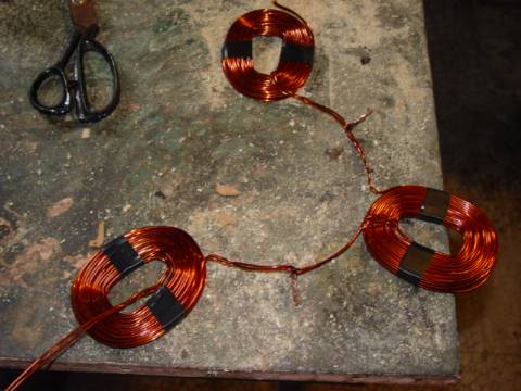
This is a nice way to wire the stators I find. It's a 3 phase stator, there are 9 coils. Each phase has 3 coils in series. It's pretty easy if we lay 3 coils (1 phase) in the mould at a time, exactly where they belong, and make the series connection. Once all 3 phases are wound, each phase then has 2 wires (a start, and an end) coming out. We can lay all 3 phases in the mould where they belong, and tape them (or use a bit of fiberglass mat and superglue) together so all the coils are held together in a rigid fashion.
Pictured above is the stator fresh out of the mould. We cast the coils in Polyester resin. The stator is 15" outer diameter X 5.5" inner diameter, and 1/2" thick. The holes in the coils are exactly located beneath the path of the rotating magnets.
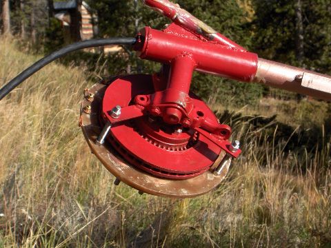
Here's a picture of the finished alternator sitting on the end of the tower just before we raised it. The alternator came out pretty nicely with a cutin speed of exactly 150 rpm (it's producing 12.5VDC on the DC side of the rectifiers at 150 rpm) You can see all the grease we put on the tower top, and on the tail pivot. Notice the wire clamp on the top of the wind turbine where the wire is clamped off to the wind turbine. From there, the wire runs down the tower.
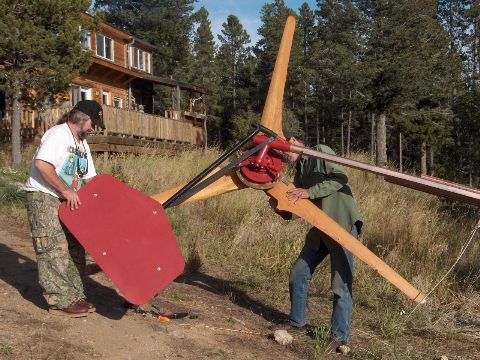
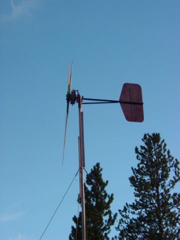
Here George and Tim are getting the tail and the blades mounted. The tail is about 6 square feet in area, the blades are 10' in diameter. Tim got off easy on the blades. One of the machines we made last winter had some stall problems (the line was very short and the wire very heavy.. and the magnets too large) , so we decided to mount a wider, slower 11' diameter blade set to that machine. So.. we had a spare set of 10' blades. My thought was that they would be a good match for this machine since the magnets are a bit smaller.
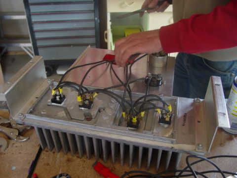
Here Tim is connecting the rectifiers together. He's made a nice 'power panel' for the wind turbine which features a huge heat sink, it should work fine. Here were using 4 40amp bridge rectifiers to rectify the 3phase current into DC for battery charging.
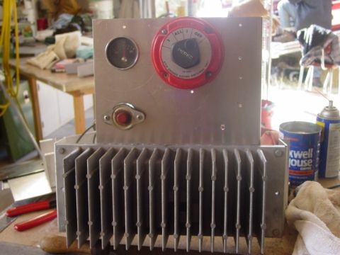
Here's Tims power panel all finished up. He put in a better meter since I took this picture.. a nice old one that shows 0 - 100 amps. Behind the heat sinks he's got his rectifiers. He's using a battery switch (a very heavy duty switch) as a kill switch, this will short out the 3 phase on the AC side of the rectifiers. He's also got a 150 amp DC breaker in between the rectifiers and the batteries.
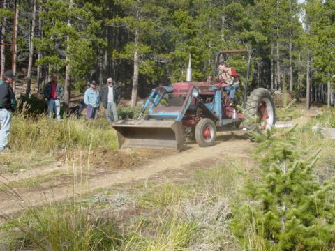
Tims tractor did a nice job of making a trench so we could bury the line from the tower to the batteries which are located in his shop. The line from the base of the tower to the batteries is #6 wire, 3 strands and we used 1" diameter PVC as conduit. It's buried most of the way. Up the tower to the machine he's got 3 strands of #8 wire. The tower is only 30' tall - but it's in a good spot. The distance from the tower to the batteries is about 50'.
For guy wire mounts, we cut 6' long pieces of 1.5" sched 40 pipe, sharpened them, and pounded them down 5'. This was... pretty tough and slow going, but I believe it's pretty strong, I cannot imagine these coming out! The guy wires are from 1/4" stainless steel cable that Tim picked up at a local metal scrap yard for a few cents a pound. (score!!!)
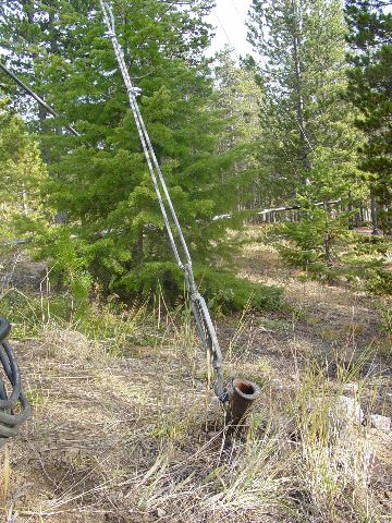
Here we've test raised the tower (no machine on it yet), and Tim is pounding down the last guy wire mount. (At this point, this side is supported by the winch).
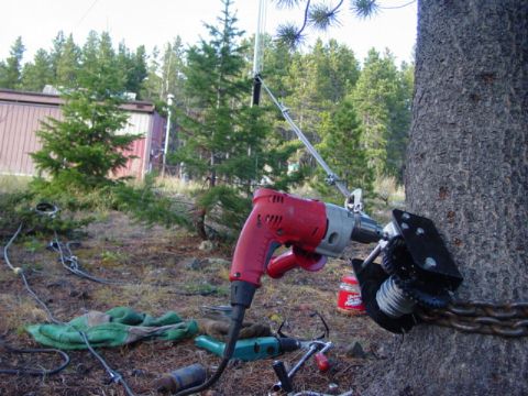
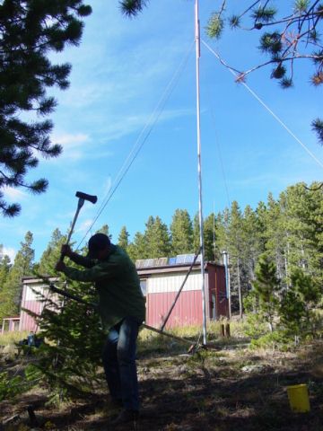
We used this inexpensive winch from harbour freight to raise and lower the machine. It's lagged into the side of the tree with a chain around it for additional safety. These winches come with a hand crank, but the shaft fits nicely in a 1/2" drill and things move along much more quickly.
Here it going up... Those trees in the background look kind of bad (and they are) - but they are doomed. Tim wants to kill these trees for the windmill, for fire safety ('cause the county insists on it) and for the veiw. Once gone.. this will be an excellent wind site.
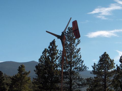
That's how it looks today, we raised this just last week. It turns very freely and seems to cutin nicely in low winds. It's been windy last few days so we've had a chance to see that it furls out nicely, and produces good power. On windy days like we've had recently, Tim's been seeing up to 80 amps from it. It seems to be a good machine. It's also almost completely silent... This was the first of the machines I've made with these smaller magnets, since this one got done we've finished one more and I have one underway. I think this is a good match between alternator, and blades so long as the line is not very resistive at all. If the line were long, or resistive, I'd be inclined to run with a slightly smaller prop, or slightly larger magnets. In this installation anyhow... things work quite well.
Click here for some pages about similar machines built over a year ago. While these pages detail the construction fairly well, there are quite a few changes. These later ones have smaller magnets, they have fewer windings of heavier wire, and they are wired in star. I've also changed a few other minor things about how I make them... but basicly they are very similar.
Click here for a page I made about some 10' machines we built last winter. These are a bit more up to date... but the magnets were still too large for the 10' machines.