Page 3
|
This page is about an older project of ours. We keep ALL of our projects up on the internet for anyone that's interested...but we are no longer pursuing many of these older ideas. Before starting this project, please check our main Wind Power page to check for similar, more recent designs. These will be the top of the list and flagged with an "active project" tag. If you have any questions about what is current and what is not, or why we no longer work on certain designs, first check out our Wind Turbine Evolution page for a detailed history of how our designs have changed over the years. You can also Email us and we'll fill you in as our email volume permits...check the Evolution page first.
|
PAGE 1
Frame fabrication and alternator design procedures
|
PAGE 2
Frame finishing and alternator fabrication
|
PAGE 3
Alternator and blade assembly
|
PAGE 4
Installation on tower and raising!
|
para Español
This is 'part 3' of the project. The goal was to build a simple 17' wind turbine, basically a scaled up version of earlier machines we've built which are very much inspired by Hugh Piggotts 'Axial Flux' wind turbine plans.
And, be sure to check out our book Homebrew Wind Power -- it has all the information you need to build this turbine.
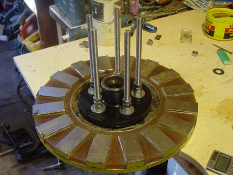
Here we're attaching the back magnet rotor to the hub. Again, we have to really be careful around these magnet rotors, the hub - wrenches... anything made of steel or iron is strongly attracted to these magnets. Notice how we're using nuts, and washers to serve as spacers between the magnet rotors. Better would be to machine a spacer, it can take time to get things perfect using nuts and washers.
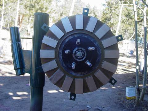
Next we grease the wheel bearings, and mount the hub, with the back rotor to the machine. Then we can adjust the bearing and insert the cotter pin into the castle nut that holds it all on the spindle.
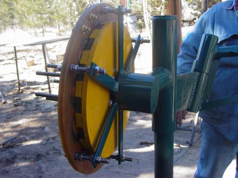
We mount the stator so there's about a 3/32" gap between it and the back magnet rotor.
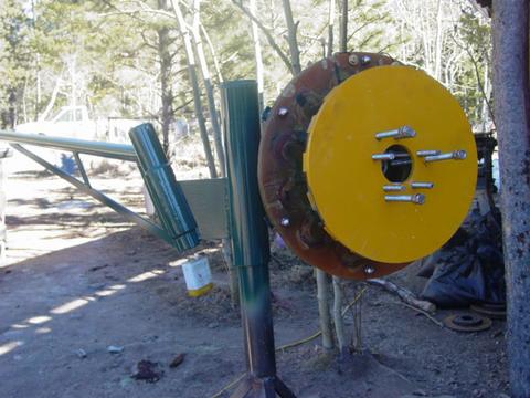
Pictured above you can see the 3 jacking screws we use to carefully lower the front magnet rotor into position. The magnet rotors must be aligned, so that wherever we have a N pole on one rotor, there will be an opposing S pole on the other rotor. When we placed the magnets down on the disks, we ground an 'index mark' into the sides of each rotor so that we can be sure to get them together properly.
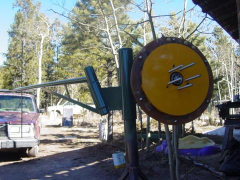
So here we have a finished machine, except for the wooden parts! At this time we could test it. The cut-in speed is about exactly 75 rpm so all is good! It's pretty impressive how stiff an alternator of this size becomes when you short out all 3 phases. If you spin it up by hand nice and fast... and then short it - there's an impressive flash (like a welder) and it 'bangs' to a dead stop instantly. Lots of fun...
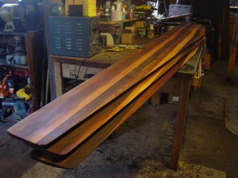
I had my freind and neighbor Scott build my blades from laminated Cedar. He has a nice wood shop, he can do them in a fraction of the time I can - and it saves a mess in my shop! We came up with a very simple 'formula' for these blades so that they'd be easy to make - and easy to replicate. They are 6" wide at the tips, about 14" wide at the widest point near the root and the taper is straight. They are 8 1/2' long to make a total diameter of 17'. They are pitched 3 deg at the tip, and 6 deg at the halfway point (radius =4.25'). This all makes the front of the blade a completely flat surface, that can be made very easily on a planer with a simple jig.
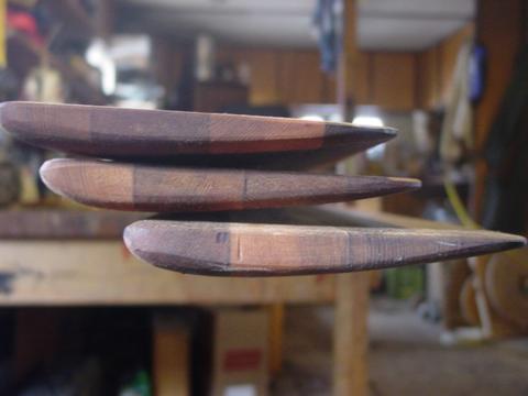
Pictured above is the tips of the blades, you can see the very simple airfoil. The thickest part of the airfoil is 1/8" as thick as the blade is wide, so at the tips we're 3/4" thick, at the half way point we're about 1.5" thick, and it tapers to maximum thickness of 2" near the root of the blades.
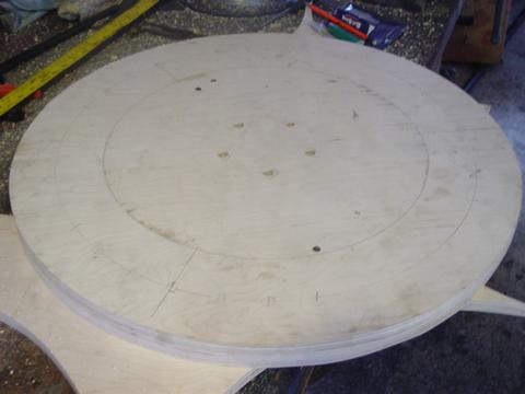
The blades will be sandwiched between two plywood hubs. These hubs are 26" in diameter and made from 3/4" thick Baltic Birch plywood. Baltic Birch plywood is super tough stuff... and it holds up well to the weather. It's much stronger than ordinary 3/4" plywood.
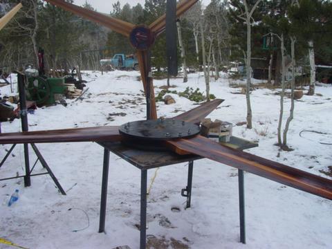
Here we're assembling the blades. I stained the hubs black and we coated everything with a thick coat of linseed oil. There are 3 bolts through the hub/blade assembly for each blade - so a total of 9 bolts help hold the blades in and squeeze this whole 'sandwich' together. First we assemble it all and just 'snug' the bolts up so that we can still make adjustments to the position of the blades.
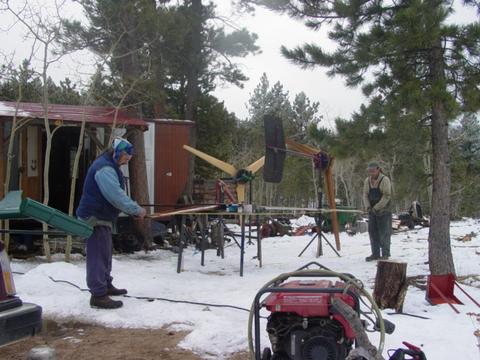
</
center> Here George and Scott and measuring tip to tip on the blades to make sure they're positioned properly. Once that's done, we can tighten up all the bolts and put in a bunch of wood screws. On this one, we have 15 wood screws into each side of each blade - through the hubs, for a total of 90 wood screws in the whole assembly.
I forgot to get pictures of the tail. The tail is kind of 'arrow shaped' - basicly its about 2 1/2' wide and 5' tall, for about 12 square feet of total area. Its made from very strong 1/4" thick Baltic Birch plywood, which we also stained black and coated with linseed oil. It's bolted onto the tail boom with 4 bolts.
So there we have it, a finished machine!
PAGE 1
Frame fabrication and alternator design procedures
|
PAGE 2
Frame finishing and alternator fabrication
|
PAGE 3
Alternator and blade assembly
|
PAGE 4
Installation on tower and raising!
|


