| We have a variety of different ideas here for science project wind turbines. Some are our own, some were submitted by readers. Check them all out before you launch into a project! |
|
Kidwind.org Science Projects
Kidwind.org is a great resource of curriculum information and hard-to-find materials for the science teacher or parent who wants to teach kids about wind power. They give seminars to teachers around the country, and their webite is highly recommended! |
Science Fair Wind Turbines by DanF
This article is an update of DanF's original article, still found at the bottom of this page. This update was originally printed in the November 2005 issue of the Energy Self Sufficiency Newsletter.From Anita: Dear Mr. Windbag: I’m a high-school student and have a class assignment on renewable energy. We have all semester to build and test a project that saves energy or makes energy, and we have to document our results. I’m really interested in wind power, and I’d like to build small wind turbine that will light up a light bulb. Where do I start?

Hi Anita.
Wind power is fun to experiment with, and not that difficult or expensive. But you should first have realistic expectations of what kind of result you’ll be able to get with how much work and expense. Another important aspect of science projects (and required at science fairs) is demonstrating your use and understanding of the Scientific Method of observation, hypothesis, predictions, testing, and conclusion. Hopefully I’ll be able to give you some good background knowledge so you can decide how to proceed with your project.
First, it would be an excellent idea to familiarize yourself with how wind turbines extract energy from the wind, and their basic components and how they work together. Take a look at Part 1 of my “Small Wind Turbine Basics article in the ESSN for the math involved – it’s very simple. Familiarize yourself with Ohm’s Law – a Google search will fill you in. There are also excellent introductions to wind power and wind turbine components at Windpower.org – be sure to take all their “guided tours”, not just the one for kids.
The two most important design issues you’ll have to decide on are:
- Can your wind turbine fly outside in real wind to test your design and gather data, or does it have to fly inside using wind from an electric fan, such as at a science fair inside a gymnasium?
- Do you only need to show and measure power output on a meter, or does your wind turbine have to do something physical like power a small light bulb or LED, or make a small pump turn?
If fan power must be used, options for your turbine’s power output are more limited. But for younger students, fan power is the best way to go – a very safe, fast and easy way to demonstrate wind power. The safety precautions needed are minimal. Fan power may frequently be the only option if the turbine must be demonstrated indoors. However, it’s very difficult to do anything with fan power besides making a meter move and measuring the results. Powering light bulbs and LEDs with fan power takes lots of extra complexity and expense – but it can be done.
The “real wind” can be from mounting the turbine outside on a tower, or from mounting it on a vehicle and collecting data while an adult drives – slowly, on a rural road with little traffic
– and calls out the vehicle’s speed. If real wind can be used for power, more options for experiments are available, but everything must be built better and sturdier.
The problem is that a small, experimental turbine designed to fly and make power efficiently in real wind won’t even start to move with a fan, while a small turbine that can turn under fan power will quickly blow apart in real wind. Wind made by a fan is very slow and very turbulent, so it doesn’t have much power available in it.
As for choosing your load, whether it’s a light bulb, LED, charging a battery, or some other type of load, it’s simpler to first choose your generator and then decide on a load. Here’s an overview to get you started.
DC Hobby Motors
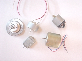 Many people decide to go this route, since a DC motor when driven acts as a generator, and it’s easy – put a rotor on a DC motor, mount it, and let ’er rip! It’s quite suitable for younger students who have not yet learned any more than the basics of electricity in class, and for classes that will not be studying electricity further.
However, there are DC hobby motors that do work at low RPM. Computer fan motors may be the right kind, but some are brushless and won’t work for this application. To test a motor, you’ll need an inexpensive multimeter (available at Radio Shack). You’ll need a multimeter for ANY kind of electrical experiment, so it will get used throughout your school career! Note! If the motor has more than 2 leads coming out, it’s the wrong kind and can’t be used! Connect the multimeter to the 2 leads and set it for DC volts in the 2-12 volt range. Spin the motor by hand and record the reading, then try spinning it with a cordless drill set at low speed and record the reading.
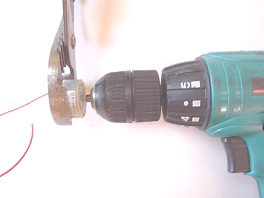
The voltage you get using the cordless drill at low speed is probably the most you can ever expect from your project. The hand-spun voltage will be more typical. Compare your numbers to the following MINIMUM voltage requirements for some common loads: Red LED: 1.7v White LED: 3.6v Flashlight bulb: 3v to 6v Tiny water pump: 3v to 6v Battery charging: Voltage of battery, plus at least 1 volt, then another 1 volt for the diode.
If you can’t get to these levels with your motor, you’ll need to find another motor to test, try one of the other gearing or generator options below, or settle for just using a meter to measure your power output. The accuracy of your data won’t suffer, only the visual drama. Analog meters (the kind with the moving needle) are much more dramatic to watch than digital! There’s also more to it than just voltage – the amperage is also important in a real-world wind power application, because volts times amperes equal Watts – and Watts are what power output is measured in. Volts are only “potential” power –they don’t do any “work” until a complete circuit is formed (like from your wind turbine to an LED). But the typical loads listed above are very low power, and most hobby motors should have no problem running them.
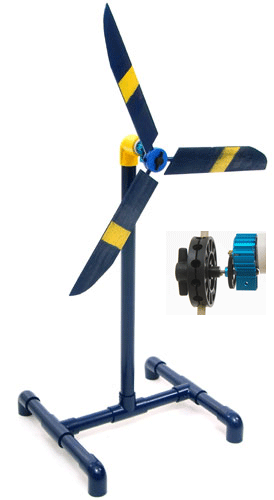
Another option is to gear up the the hobby motor to make it spin faster. Michael Arquin of KidWind.org came up with a really clever geared hobby motor system that boosts the output in the 1.5v-3v range, enough for almost any application, including water pumps, charging batteries or tiny demonstration hydrogen fuel cells, and a large variety of lights.
You can order his kit from the KidWind Store. The gearing makes it harder to get the blades spinning but, once they are moving, the power output is excellent.
There are plenty of sources for hobby motors in addition to KidWind. You can find them at local Radio Shack stores, online retailers like All Electronics, C&H Sales, and MECI – and even by disassembling your little brother’s motorized toys!
Keep in mind that if you want to charge batteries with your experiment, you’ll need to put a diode in the line to keep the batteries from just spinning the motor—and the diode will drop your output voltage by about a volt.
Homebuilt Alternators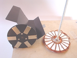
>While hobby motors are a quick and easy option, you can see their limitations ... primarily the high RPMs needed to get useful power out of them. If you have the time to spend, or are a more advanced student studying electrical theory, a homemade alternator can be an excellent choice. The unit can be designed from the start to generate usable voltage at low RPM! The most interesting alternator kit I’ve seen is a small 3-phase unit available from our friends at Windstuffnow.com. The price is reasonable, and during my tests the performance was good enough to light LEDs under table-fan power. The unit is designed with a simple, easy to build vertical axis blade design, and it can be converted to horizontal axis.
Michael from KidWind has already successfully tried this. The rectifier diodes to convert the 3-phase AC output to DC are included in the kit, and I recommend it highly.
Another kit option is the PicoTurbine, with both a kit and freeon-line plans available. It’s also a vertical axis machine, though it would be harder to convert to horizontal than the Windstuffnow design. If you are interested in designing and building your own small alternator from scratch, a good place to start is reading through my Hamster-Pow- ered Alternator pages for a design that can light LEDs at only 40 RPM – it was originally powered by Skippy the Hamster, but could be easily converted to wind power instead of rodent power.

Tape Drive Motors
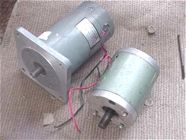
Some larger tape-drive motors are powerful enough to get you into the realm of real wind turbines, with rotor sizes ranging from 3 to 5 feet in diameter and generating significant power. Such designs must be extremely sturdy, and can be quite dangerous in higher winds. So, this scale of project is best suited for a teacher and entire class to undertake, or an older, advanced student with experienced help. Some of these designs can produce up to 100 Watts in output at 12 volts! Perfect for charging a deep cycle marine battery.
UPDATE--03/18/06----- Kit, plans and parts now available for a 4-foot, 100 Watt turbine.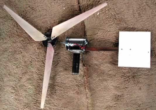 It looks really slick, and uses a treadmill motor as a generator, with blades cut from PVC pipe. You can buy all the hard-to-find parts, or an entire kit, from the designer--click the photo above, or go HERE to velacreations.com. The plans are free and published on their website, if you want to scrounge up the materials yourself.
To us, this looks like a great way for a high-school or junior-high student (who maybe caught the wind power bug building a tiny, science fair turbine in elementary school) to step up to making some real power that can charge a 12V marine deep cycle battery. And of course a great, inexpensive introduction to home-brewed wind power for any curious adult!
More On Fan Power
For fan power, you’ll need large, wide blades to get enough torque out of the limited wind to start things spinning. Blades salvaged from a table fan or homemade balsa wood blades, such as these shown here at a KidWind Seminar, are a good place to start experimenting. KidWind.org Turbine Parts also sells machined plastic hubs so students can experiment with different numbers of blades easily. With fan power, the blades won’t get spinning fast enough for lift to help performance, so airfoils and twist won’t make any difference in performance—though you might want to include these elements for demonstration purposes.
Here we come back to the issue of fan versus real wind power. In a good, efficient wind turbine design, the blades will be matched in size to the generator’s output in lower, more normal wind speeds. If the blades are too small for the generator, it will be difficult to start and will stall in higher winds. If the blades are too large, the generator won’t be able to extract enough energy, and the turbine may fall apart in higher winds!
None of this is an issue with fan power, but the problem then is that there’s very little power available, and a good design for real wind would most likely not even spin under a fan.
A good design for real winds would resemble the blades in this photo – skinny and thin at the tips with only a small pitch, and thicker and fatter at the root with as much pitch as the wood thickness allows, plus an airfoil carved on the back for lift. These blades were made with a CAD machining system by a friend, contact me at My Email address if you are interested in trying a set.
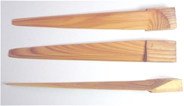
Wide, multi-bladed designs, while great for fan power, will often break in real winds – however, testing different blade designs in real winds makes for an excellent experiment.
In my experience, computer fan blades are too small to work well in either real wind or fan power—they don’t sweep enough area to get spinning rapidly enough. Model airplane props are also marginal—they must be reversed (the curved side faces back in a wind turbine blade) and that also reverses the airfoil. They are also difficult to get started spinning. Instead, I recommend carving your own blades or trying a set of the wooden ones similar to those shown above. We have some information available about blade design and carving for our big 10-foot wind turbines that can be scaled down for sceince fair blades. It's located HERE. Another good source of free blade information is at Scoraigwind.com.
Measurements and Meters
Once you have something working, whether from fan power or wind power, you’ll need to take measurements. In many experiments, only the output voltage is measured. This gives a direct correlation to how fast the blades are spinning, but is only part of the story. Watts (volts x amps) are the important figure, and measurement requires a load. The amperes will be determined by how large a load you attach – how many LEDs or light bulbs, for example. If you built a system good enough to charge batteries, your load will change with how full the batteries are.
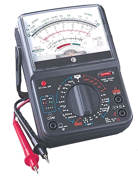
What you measure and how are dependent on the goals of your project. A digital or analog multimeter (for volts and amps) might be all you need. For an advanced project, you could even get a computer-interfaced multimeter (available at Radio Shack) that connects to a PC for data logging!
Here's another very interesting science fair wind turbine design.
In fall 2005, Glen Hurd posted a very fun, educational, and simple tiny wind turbine design on the Otherpower Discussion Board , and gave us permission to use it. Glen’s business is the manufacturing and wholesaling of custom LED lighting products and solar power systems. Thanks Glen!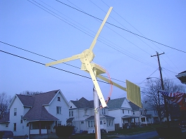
This was a lot of fun. There was no stress about anything really needing to work, but it does! It started as killing time with stray parts, and grew into a simple little mill that has potential for a nice paper and project about wind power, from permanent magnet power generation to blade design.
The 3 phase permanent magnet alternator is from a VCR. Only the bottom plate of the VCR was removed for the photo. Most of these motors are held in with 3 screws from the top, and are very easy to remove. First unplug the wires connecting the motors.
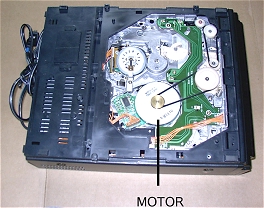

The large disk on the front of the motor was held in place by magnets and a small plastic washer on the axle. Often the shaft can be pushed, removing the assembly as the washer slides down the shaft, but sometimes they need to be cut off. Save the washer if it comes off easily.
There seem to be 2 common types of this motor. The bad motor is subject to very strong eddy currents in the metal backing plate, and is not very usable because as the RPMs increase the drag increases to an extreme amount.
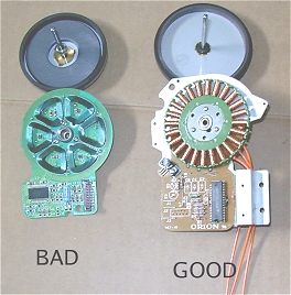
These motors are wired in 3 phase star, meaning the 3 phases are connected together in one place, and each of the 3 phases have the other end going out of the motor. An Ohm meter is needed to tell where the 3 motor output wires are located. The ‘good’ motor in the photos has the common connections and output wires very easy to see and connect wires to. The traces or conductors on the circuit boards were scraped away with a utility knife, just to be sure no power was being fed to the circuits. The ‘bad’ motor had 3 holes drilled to get the wires out the rear. Output wires are soldered to the ends of each phase.
Dan’s note – for a detailed explanation and diagrams of 3phase stator wiring, take a look at Windstuffnow.com’s 3 phase basics page. You might also give this discussion board posting a look.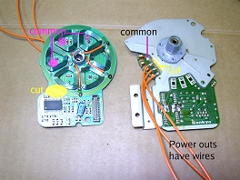
Each phase has the same Ohm reading. This ‘good’ one is about 4 ohms, so from the common to any output is 4 Ohms. From any output to any other output will be 8 Ohms.
From any common to any other common is about 0.4 ohms, but that is from the wires on the meter, and is almost the same as the ohm meter itself from test lead to test lead.
Now seems like a good time to show the lighting wires. Red LEDs light quite easily, and I recommend only red LEDs. Other colors need higher minimum voltages to light up, and draw more current. LEDs only pass current in one direction, but the alternator makes current back and forth (Alternating Current), so each section needs a pair of LEDs connected backwards from each other. The resistor is to limit current so the LEDs do not burn out, but will have very little effect on the LEDs lighting up. LEDs also have the advantage of not conducting any current until they reach a certain voltage, and that helps get the windmill turning before there is a load dragging the speed lower. A regular light bulb will result in very poor, if any, operation. It can be fancy or simple, but the wires cannot touch each other where they shouldn’t.
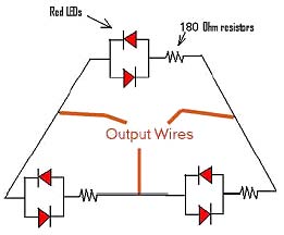

After the soldering is done the large disk with the magnet ring is replaced and a quick spin of the shaft should light the LEDs!
Now onto the blades.
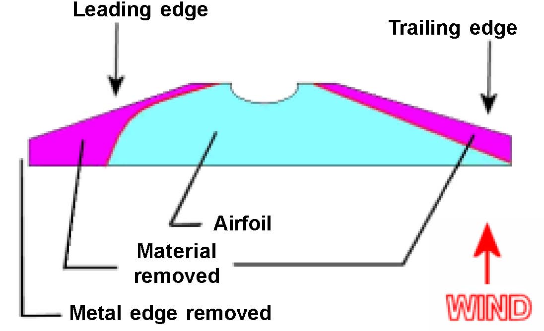
Wooden rulers make simple blades. Part of the angles are ready to use! I removed the metal strip, marked and cut off 3/ 16” along that side, from 3 and 1/2" to the end. The blades are sanded for a trailing and leading edge. A bench mounted sander will make things faster and easier. The root, or center, is not changed. The root angle is needed later for fastening to the hub.
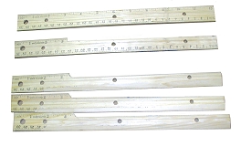
Ruler Windmill Blade Toward generator
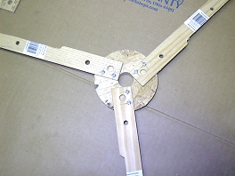
A hub holds the blades together and on the front of the alternator. It is not a motor any more!
This hub is a donut of wood 3/4" thick. Use smooth, good wood. The chip board in the photo caused some problems later. The center hole is as close to the pulley diameter as possible. A set of hole saws helps make the hub easier.The hub is marked with 3 lines 60 degrees apart. Each line is marked twice and small holes drilled for screws that will hold the blades. The blades are marked and drilled with a bit that is a little larger than the screw threads. Now the blades can be attached to the hub. The more accurate everything is done the better. The hub should now fit over the alternator, and the blades should look something like this.
WIND
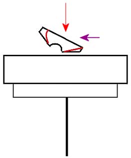
Some rulers have a lower or higher angle than others. This set of blades has 2 layers of a business card under one side of each blade to increase the angle as viewed from the end. About 8 degrees seems like a good angle. After the blade angles are adjusted if they needed it, a bit of wood glue is a good idea.
Now for the frame to hold it all together.
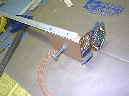
This shows the main piece of wood with everything attached. The center is drilled for a 5/16” bolt about 3-1/2" long. The bolt is placed in the hole, then a washer (so it turns smoothly), then a tight nut. Next, another nut is screwed half way up the bolt. The end of the bolt, on the side, was smacked with a hammer to badly damage the last 3 or 4 threads at the very end, and the second nut was screwed toward the end until it is firmly held in place by the damaged threads. Then the alternator was screwed to the base.
A suitable tail and tail boom were then assembled from scrap paneling and moulding, and attached. A good quality double sided foam tape holds the hub to the magnet rotor and shaft.
That is why wood is better than chip board... nothing seems to stick very well to chip board, and chip board is damaged by water sooner. The blade assembly is then slid back into the alternator.
Next, blade balancing is needed. One side will probably come to the top, again and again, after a few slow spins. The top is the lightest side, and a little extra weight to that side will help the windmill run much more smoothly. A rubber band around the hub, holding a couple washers or maybe a nut, should show how much weight is needed and where. The weights can then be screwed to the hub. Don’t rely on a rubber band to hold any weights, because it will not!
This ‘tower’ is a section of 1/2" metal conduit. The photos show the 1/2" conduit inside a piece of 1" copper at the bottom because that is one of my test towers. The windmill nuts and bolt are simply placed in the conduit.
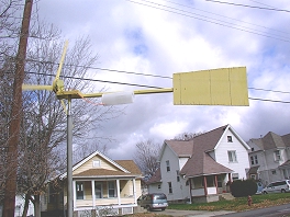
This windmill can make about 8 or 9 volts AC per phase under a load of about 25ma when spun by a flick of the fingers. I have no idea what the RPM is at that time. These LEDs were placed in a half clear plastic tube in the first photo. The whole thing lights up very nice on a dark windy night.
Red colored plastic red LEDs are hard to see lighting up in daylight. ‘Water clear’ red LEDs show up when lit the easiest, by far, because as soon as they light they turn red!
The blades could be a little shorter, maybe about 10” each, or even 9" for this particular alternator. Then the windmill would spin a little faster and the LEDs would light up sooner. This particular windmill needs about 14 miles per hour wind, steady, not gusting, to light the LEDs with the 12" blades and 24” diameter. Different alternators will perform differently, so your mileage may vary!
The blades do not spin very fast at all in front of a fan. The air is too turbulent. They work far better outside. These blades could surely be improved upon, but these are easy to make, work well, and have a decent airfoil, good enough for a school paper.
It is very hard (I can not do it at all) to light the LEDs by hand spinning the shaft after the blades are attached. The LEDs light very easy without any blades. For a school project that must be deomnstrated indoors under a fan, you might want to have an alternator for the windmill, and an extra to light the LEDs by hand, just so everyone can see it light up!
Accurate blade placement and making all the blades the same is important, it seems quite important for a decent balance. Good balance is important for the windmill to start turning in a low breeze. Danger! These blades get turning very fast. A blade that flies from the hub or hits a person will hurt, and could cause injury. Be safe!
My next plan, if the coils can be removed, is a dual rotor alternator with 2 of the same magnets, or maybe HD magnets, mounted on speaker plates. The speaker plates will be drilled and threaded for all-thread shaft, and a set screw will be added. The air gap and magnet disks will be adjusted by turning the disks so the magnets line up, then tightening the set screw. There is no need for jack screws from disk to disk, the magnets are not dangerously strong. This should allow for maximum area in the center, and use of common bearings. Finding suitable bearings are always a major problem for me.
>Dan's note: http://www.fieldlines.com/story/2004/10/4/22201/3047 This discussion board posting shows 2 more tiny alternator designs, much like what Glen wants to try on his next one. Be sure to scroll all the way down the thread to see photos of these clever designs! The homebrew wind power enthusiast community has some extremely ingenious people, and I’m glad our readers have had a chance to meet some of them. Thanks again, Glen, and all of the other Otherpower Disscussion Board regulars too.
Vern Van Zandt's homebrew permanent magnet alternator
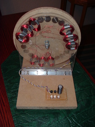
Completed homebrew permanent magnet alternator
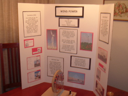
Display at Vern's son's science fair booth
by Vern Van Zandt
I had a pretty good chuckle reading about the Hamster powered night-light on the Otherpower projects page. It was also good inspiration for my 10 year old Son's science project at his school. His subject was wind power, the history, uses and present state of the technology. I also thought it might be good to build a small PMA to demonstrate to the other kids at his school just how electricity could be generated. I had never built PMA before, but had a real itch to do so. So I set about building a small 'hand crank' version that uses the same size and type of magnets as the night light project, and #28 wire.
Design Goals:
- To provide a working model of a permanent magnet alternator (PMA) that could be SAFELY actuated by kids, teachers, parents, etc.. For this reason no prop blades will be placed on the rotor, fearing injury to young fingers, etc. Rotation of the rotor can be acomplished using a crank handle instead.
- Provide a simple, safe, and intuitive indication that the PMA is generating electricity.
- [NOTE TO THE READER: This PMA was never intended to be used as an actual wind machine! The materials used can not be expected to withstand long term use in the outdoors. It is strictly for demonstration purposes only... The selection of materials were based on what was on hand, and that could quickly be pressed into service.]
This PMA (Permanent Magnet Alternator) is intended to be a 3 phase unit using 3 series coils in each leg of a star configuration. Each coil has 300 turns of #28 enameled copper wire. The 3/4" x 1/8" magnets were stacked two deep in each position of the wheel, roughly 15 degrees apart (360 degrees / 24 magnets = 15 degrees/magnet). I didn't have any steel handy to fashion a backing plate, so the magnets were simply embedded in the wooden rotor. A steel plate would have increased the effectiveness of the magnets. Something for a future PMA perhaps. The rotor wheel is simply a piece of 1/2" thick MDF approximately 9" in diameter. This was something that I had left over from another unrelated project.
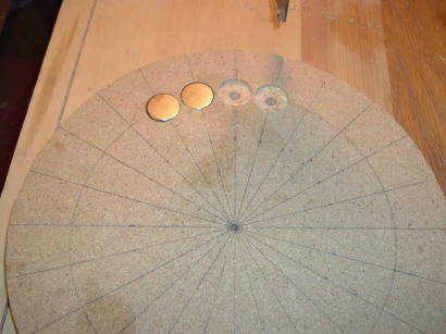
I used a degree wheel to mark the radial position of each set of magnets. (photo) 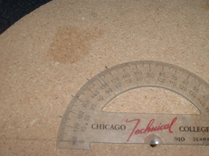
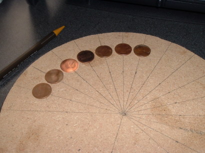
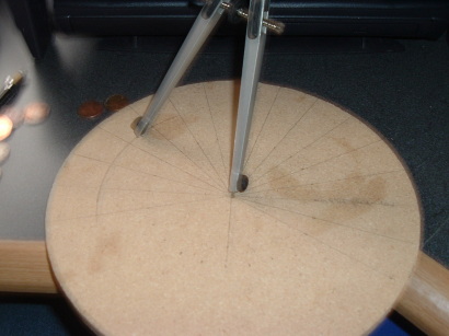
Once you've established a circle of pennies, use a compass, string and a pencil, or whatever you have that will draw a circle through the center of the pennies. The point at which the line crosses the circle defines where you drill a 3/4 inch hole (photos below).
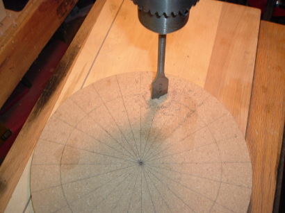
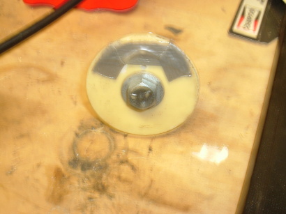
Making the coils was easy once I came up with a way to automatically count the turns. I didn't have a lot of time to put this together, and I knew that if I tried to count hundreds of turns of wire, that I'd eventually mess it up and have to start all over again. I also didn't have time to build a proper wire turning machine. What I came up with was to build a coil form out of a 3/8" x 4" hex head bolt and a bunch of washers . I could chuck it into my drill press, and with a way to suspend the spool of wire feed it as the form rotated. The slowest that I can set the drill press to turn is 250 RPM. This was just about right for winding the coils.
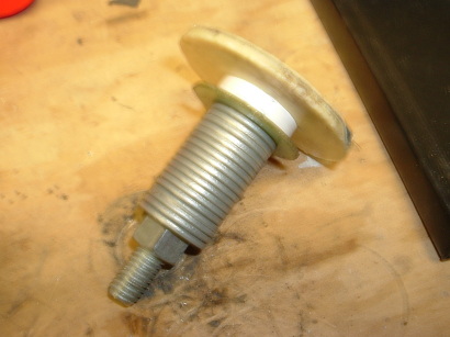
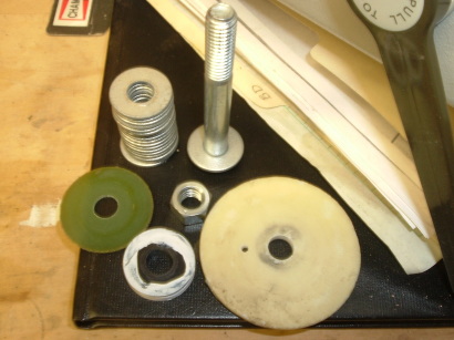
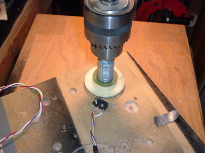
A small micro-switch (Radio Shack #275-016A) was mounted on a piece of plywood, and connected to the counter via a battery, capacitor, and diode to a HP Universal counter(photo at right). 
Now I do realize that not everyone is going to have a universal counter just laying around the house. It just so happens that I also dabble in electronics as a hobby, and this one was procured several years back from a surplus supplier in California. The nice thing is, that it can be configured to count electrical pulses. By mounting a small cam to the bottom of the spindle to index with, or 'trip' the switch each revolution, I could simply turn on the drill press and feed the wire, watch the counter, etc.. This was still a bit of a juggling act, and several times things went wrong. But for a quick and dirty method, it worked well enough. When everything went correctly, I could wind a coil in a little over a minute. There are small LCD counter modules available from Red Lion Controls (like the 'Sub Cub', for example), and others, that should provide the same function provided you want to build something similar to what I used.
Once the coil is wound, placing a small piece of duct tape over the coil to hold the free end of the wire kept the coil from unraveling from th form. At that point the coil form could be removed from the drill press. A small amount of children's rubber cement on the coil was enough to hold the turns in place while the bobbin or coil form were disassembled. Teflon tape around the 1 inch form helped prevent the coil from sticking to the form during removal. Still, removal of the coil probably required the most time, but produced some reasonably uniform coils. A couple of narrow strips of duct tape were wrapped around opposite sides of the coil to further hold windings together. Since the coils were circular at this point, I 'squished' them to make a somewhat oval shape that fit the width of the magnets. I suppose that a smaller diameter coil might work better (?), but a 1" form was all that I had (photo) 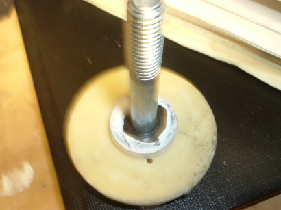
The finished coils were then sandwiched between two 1/4" thick sheets of clear plexi-glass so that the magnets could be seen as they pass each coil (photo) 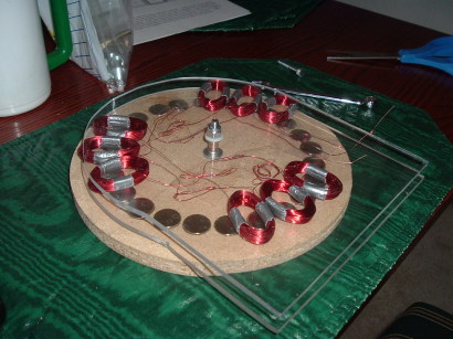
Placing the coils was accomplished by laying the rotor flat with the magnet side turned up. One of the two pieces of plexiglass was placed over the rotor, and the coils were then placed so that there are four magnets for every three coils (photo). 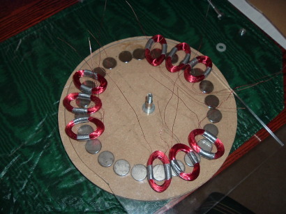
In theory this also allows for a total voltage at least three times that of a single coil. In practice, it also depends on correct phasing of the coils with regard to the magnets. [Those of you who have already built one of these certainly understand this much better than I]. Once the coils were positioned and connected, two inch wide clear tape was used to hold them in place. At that point the second piece of plexi was placed over the top of the first. I also assembled the bearing on the hex bolt 'shaft' as the sections were joined (previous photo).
One big challenge was how to quickly, cheaply, but effectively mount the rotor so that it could be turned and also maintain a fixed distance to the magnets. I eventually used a small Bronze bushing that just fit over a 1/4" hex bolt. Using a variety of washers and some Lithium grease, I was able to suspend the rotor in front of the coil - plexi 'sandwich'. The bolt extends through the entire width of the machine and is secured with a lock nut. The bronze bushing also extends through the entire width. 'End play' was adjusted using washers at each end of the bolt, in addition to tightening the nut. This allowed the rotor to turn without allowing the bolt to slide back and forth exessively. A nylon washer (or two) between the rotor and the plexiglass gives the two pieces sufficient clearance for rotation of the rotor, and minimal contact.
I also assembled a circuit board with two bridge rectifiers, a 3300 uF cap (to act as a bit of a storage reservoir and filter), and three LEDs (photo) 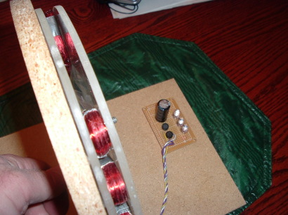
With exception of the wire and magnets, everything else used in this project was obtained at the local hardware store/home center and Radio Shack.
The alternator really does a surprisingly good job of lighting 3 high intensity LEDs (connected in parallel) and still maintaining about 2 volts loaded. Unloaded voltage was around 3.5 . By turning the handle and then counting revolutions for ten seconds, I was able to estimate the RPM at around 150.
One down side if you will, was that the clear packaging tape wasn't as good a choice as I'd hoped for securing the coils and some of them sagged or fell out of position. When this happened the alternator seemed no longer capable of lighting the LEDs. I would venture to guess this was because the phasing was disrupted enough that some of the currents bucked rather than boosted the energy developed by the remaining coils.
All in all however, this small PMA was a fun addition to my son's science project(photo at top of article), and the kids appeared to be genuinely amazed when the LEDs glowed bright red. 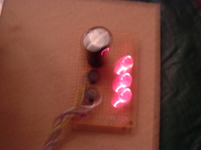
My thanks to Dan Fink for inviting me to write about this, and for putting it up on the Otherpower web site. I think it's a great site for anyone even casually interested in building PMAs , regardless of how they are driven. It is hoped that this article is of interest to others as well.
| The rest of this page is about an older project of ours. We keep ALL of our projects up on the internet for anyone that's interested...but we are no longer pursuing many of these older ideas. |
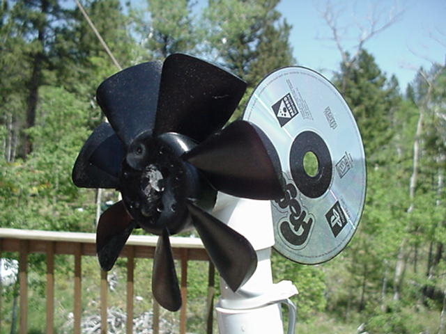
The frame is made of PVC pipe, the tail from a video game CD, and the rotor from a computer fan. The generator is a small DC hobby motor. It will light a small bulb using an electric window fan for power.
How to build some very simple demonstrations of wind-generated electricity
UPDATE 6/1/2005 -- DanF attended a seminar put on by KidWind.org, hosted at NREL's National Wind Testing Seminar. The kidwind folks are out there giving seminars around the country, teaching teachers how to teach kids about wind power, with hands-on experiments.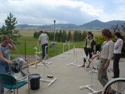
Kidwind seminar at NREL NWTC, Golden, CO, 2005
Michael Arquin of KidWind also found a great little motor for these experiments--many folks have trouble finding suitable DC hobby motors. He also came up with a gearing system so the motor will spin faster with a table fan. Plus machined hubs for easily blade mounting and adjusting their pitch. All available for reasonable prices at the KidWind.org Store.
Ed Lenz of WindStuffNow.com recently came up with a REALLY cool science fair size wind turbine where you build your own 3-phase alternator. This takes the project to the next step, so students can get into the electrical theory behind wind turbines too. The kit is available for a reasonable price HERE.
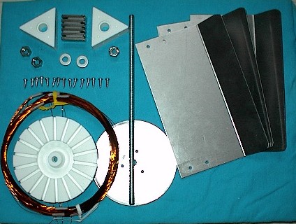
UPDATE 12/2003 -- we have received all kinds of email about this project! Some folks have been successful (CLICK HERE to see pictures and graphs....) and others have had trouble. In almost all cases the problem is finding a suitable little motor.....if the motor needs very high rpms to generate power, it won't work for this experiment. Testing the motors you have available by spinning them by hand into a voltmeter will give you a good idea of if it will work or not. You want good voltage at low rpms.
You might also want to check out our Hamster-powered alternator. Since Skippy the Hamster could only produce low rpms on his wheel, we custom-built this little alternator to work in the 40-60 rpm range. This makes it very suitable for wind or hydro experiments.
The intention of this project was a quick, small and easy windmill that would be buildable by a kid with very little adult supervision. It seems to be science fair season all year 'round up here at Otherpower.com headquarters. We get many requests for information about science fair projects, and hope this page will help kids and adults alike...at heart, all the Otherpower.com staff are kids! As a result of the experiments, we've come up with a variety of different ideas for science fair projects. The current projects on this page are very simple thanks to the use of small DC hobby motors as generators. The only test equipment you'll need is a cheap DC multimeter, available for $5-$15 at Radioshack. These projects are suitable for even a 3rd-grade science project (with adult supervision, of course). We hope to add some more complicated wind projects in the near future, involving more advanced students building their own alternator by winding coils, attaching magnets, etc. For more detailed research information regarding wind power (you'll need lots of background information for a science fair project!) we suggest searching GOOGLE for 'wind power,' and checking out some of the web pages listed in our Wind Links. The Basic Parts of a Wind Generator Even in a giant commercial wind generator that puts out thousands of watts of electricity, the basic parts are still pretty much the same as in a toy wind generator!
- Rotor--The blades and hub (the part that holds the blades on), which begin to spin when the wind gets above a certain speed. This is called "start-up" speed. The blades get their energy from slowing down the wind, extracting energy from it. Most commercial wind generators have 2 or 3 blades. Some only have 1 blade, and a counterweight for balance! More blades make a wind generator start up more easily in low winds, and give higher torque but with a lower rotation speed. Fewer blades mean harder start-up, but better performance at high wind speeds and faster rotational speeds. The backs of the blades have an 'airfoil' on them, shaped just like the top of an airplane wing or the front of an airplane propellor. This airfoil provides lift, which allows the blade tips to spin at a speed that is FASTER than the actual wind speed.
- Generator--The component that makes electricity when it is spun by the rotor. Some wind generators produce alteranting current (AC), in this case the component is an 'alternator.' Wind machines that produce direct current use a 'generator.' In both cases, however, the electricity is produced by magnets moving quickly past coils of wire--or coils of wire moving quickly past magnets. The hardest part of selecting a generator for a commercial OR toy wind generator is the rotation speed required to put out the amount of electricity you need, at a certain windspeed. More on this later!
- Tail and Yaw Bearing--To effectively slow down the wind and harvest power, the wind generator must always face directly into the wind. The tail (properly called a 'vane') lets the wind itself point the machine correctly, and the yaw bearing is simply the assembly that lets it rotate.
- Model Airplane Propellors--One of the simplest options is to buy an inexpensive ($3 to $6US) plastic or wooden 2-bladed model airplane propeller, and mount it backwards. It will style your machine like a commercial wind generator. Good sizes range from 8 to 12 inches in diameter. In a wind generator, the flat sides of the blades face into the wind, and the airfoil sides face away from the wind, the OPPOSITE of an airplane propellor. However, a quick experiment shows the problem with reversing the propellor...suspend the propellor on a straightened paper clip, and blow on the flat sides. The airfoil is pointed the wrong direction...it's opposite the direction of rotation! However, upon close inspection of the propellor, you'll also see that the airfoil carved into it is very minimal...just barely an airfoil at all. Because of this factor we've found that model airplane props still work just fine for this experiment. However, they are hard to get started with an electric fan because of having only 2 blades. You should be able to get one started at around 15-20 mph in a vehicle or in the wind, depending on the generator and prop size.
-
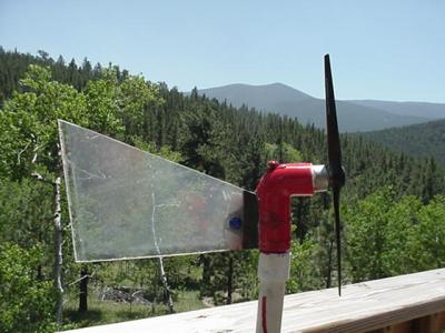
Windmill built with 2-blade model airplane prop mounted backwards. Though this unit works while testing in the wind or from a vehicle, it will NOT start up in the wind from a box fan...for that you need to use a computer fan blade prop.
- Computer Fan Blades--These multi-bladed units are an excellent and cheap option. The multi-bladed design allows them to start up very easily, at mere walking speed or in front of an electric box fan. Old computer fans are easy to scrounge up for free, and are also available at electronics stores. A diameter of 4 to 6 inches will work well. The hardest part is removing the blade from the fan assembly...since the assembly has to turn into the wind, you can't really use the bracket that contains the fan. Adult supervision is required for removing the fan blade, it may take some cutting and prying. But it's well worth it!
- Portable Fan Blades--Removed from cheap desktop electric fans, these usually have 4 or 6 wide blades, and also work very well. A diameter of 4 to 6 inches is just right. Again, supervision is needed for removal!
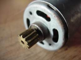
Be sure to get hobby motors with a sprocket like this already attached -- it makes things MUCH easier!
Initial Assembly and Testing Better to make sure things will work right for you before assembling the whole thing with glue! Carefully drill a hole in the EXACT CENTER of the fan blade hub, slightly smaller than the diameter of the sprocket. You want the teeth of the sprocket to catch the plastic or wood of the blade hub. Gently heating the plastic of the hub with a match will soften it and make this operation simpler, and allow you to test it before gluing it in place.Now, connect the wires from the hobby motor to your DC voltmeter. Set up your fan, turn it to low speed, and hold the motor and blades up to the fan. Wear gloves and eye protection for this operation! Once the blade comes up to speed, record the voltage you get. Turn the fan up to high speed, and again record the voltage you get. This information will allow you select your lightbulb for the demonstration.
Radio Shack has a huge variety of flashlight bulbs in different voltages. LEDs can also be used, but must be hooked up with the correct polarity. LEDs also light up with much less electrical current than incandescent flashlight bulbs. The polarity doesn't matter with flashlight bulbs however. Either one will burn out if you apply too much current from your wind generator! Pick a bulb that has a rated voltage very close to the MAXIMUM voltage reading you got, with the fan at highest speed. Attach the bulb to the circuit in place of the voltmeter, and try the test again. If all goes well, the bulb should glow brightly at the fan's top speed, and glow dimly at lower speeds. This will let you show differing power output with different wind speeds. At this point, you are ready to assemble the final version of the wind generator.
Final Assembly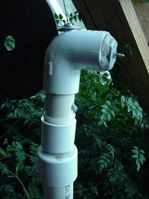
Details of frame construction are visible here, including the yaw bearing
Our frames were built using PVC pipe and fittings. Since hobby motors come in different sizes, you'll need to pick a pipe diameter that allows you to slide the motor into a pipe end or fitting. In our designs, the motor fits into a PVC elbow fitting, and is held in place with epoxy putty. Once you find which pipe diameters you need, purchase a variety of components -- 2 or 3 feet of pipe, and a few elbows, caps and reducers. Generally, the pipe and fittings fit together tightly without the use of glue, but you might wish to use PVC cement on your machine after it is together and working.
The yaw bearing can be built a number of different ways. Be sure it allows the machine to turn freely or it won't yaw into the wind correctly. Our design was very simple -- we ran a 4" long bolt down through the top, fastened underneath the yaw bearing to a pipe cap. There are undoubtably many easy ways to improve this -- we simply used what fittings we had available to make things quick and easy.
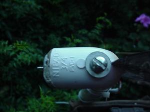
Top view showing yaw bearing bolt
The tail should be made of thin plastic, and can be of a variety of shapes and sizes. Look at pictures of commercial wind generators for good ideas on proportions and lengths. The dimensions and shapr not critical--we found that a Playstation 2 CD made a fine tail, and it expresses DanF's opinions about kids, videogames, books and science experiments quite ironically!
To mount the tail, use a hand saw to carefully cut a vertical groove in the back of the right-angle pipe fitting into which your motor will mount. The groove should be wide enough for your tail material to slide into.
Securely connect your power wires to the connectors on the hobby motor. Depending on the kind of connector, it might be best to solder them on. Adult supervision needed for this please! Then, run the wires down through the 90-degree pipe fitting, and out a small hole you've drilled in the side of it. Securely fit the motor into the fitting. You'll have to choose the size of pipe you use depending on the diameter of the motor you selected; that's why we don't give specific diameters of pipe here. Use a thin 'rope' of epoxy putty to secure the motor in place. This is the kind of epoxy that comes in a stick, and feels like modelling clay. You simply knead the 2 parts together until they blend, lay it in the gap between the motor and the fitting, and wait for it to set.
The easiest solution for how to run the wires is to mount the lightbulb directly to the upper frame or tail of the wind generator. If you want to have the lightbulb separate from the wind generator or want to use a voltmeter for your demonstration, just make a loose loop of wire near the yaw bearing, and use tape or a cable tie to keep it from hitting the rotor as it spins. This loose loop can wind itself up around the pipe mount, but will also unwind itself when the wind (fan) changes direction.
Experimental Ideas
There are a variety of different experiments that can be performed once your wind generator is operational. You can change the fan speed to show the increase in power using your voltmeter or by how brigth your bulb or LED lights up. You can change the facing of the fan to show how the tail makes the unit yaw into the wind. If you want to charge small batteries with your unit, you'll need a small diode, available for under a dollar at Radioshack. Get a diode rated at around 1 amp. The diode acts as a one-way valve for electricity--without it, your batteries will simply spin the motor and prop. You want the power to flow into the battery, but not out.A great way to test a small windmill is with a vehicle -- that way you don't have to buy or make an anemometer to measure windspeed. If you do test in a vehicle, either build a mount in the back of a pickup truck, or have someone hold the unit carefully out the car window. This could be somewhat dangerous! The person holding the unit should wear thick leather gloves and eye protection incase the prop flies off! If the unit starts to become unstable, have the driver slow down immediately. It helps immensely to have a thrid person in the vehicle to write down the speed of the truck as the driver calls it out, and write down the voltage reading at each speed.
We urge you to have fun with your project and hope our ideas have helped. However, PLEASE be safe in your experiments and wear eye protection and gloves when you are near spinning props! And remember, adult supervision is required.
About the project that was previously pictured on this page
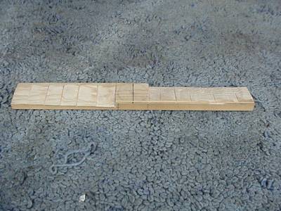
Not much more than a handsaw, chisel, and sandpaper is needed to carve a 16 inch prop!
For more sceince fair project ideas, check out Super Science Fair Projects for lots of ideas, and great information on the 'scientific method' of hypothesis, experiment, and conclusion--essential for winning a science fair.

