| This page is about an older project of ours. We keep ALL of our projects up on the internet for anyone that's interested...but we are no longer pursuing many of these older ideas. Before starting this project, please check our main Wind Power page to check for similar, more recent designs. These will be the top of the list and flagged with an "active project" tag. If you have any questions about what is current and what is not, or why we no longer work on certain designs, first check out our Wind Turbine Evolution page for a detailed history of how our designs have changed over the years. You can also Email us and we'll fill you in as our email volume permits...check the Evolution page first. |
We made a deal with our good freind Ward. Going into Dec, with only one solar panel, it seemed maybe he could use a bit more power! We agreed, that if he'd foot the cost of the tower, and wire, and help in the construction, we'd offer the shop space, parts, and some help to build a new wind turbine from scratch. It's an experimental design, and the alternator is designed around the front wheel assembly of an old Volvo 122s. Click Here to read about details and the construction of the alternator! Although it's not terribly efficient, we see about 60 amps into a 12 volt battery in a 40mph wind - so it makes significant power.
Para Español, traducción de Julio Andrade.
Please be patient, this page has a lot of pictures!
The Alternator
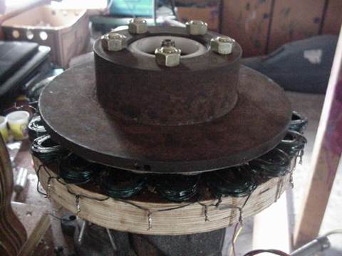
It's a radial alternator, designed around a volvo disc brake, wheel hub, bearings, and spindle. The Volvo wheel bearings make for a very tough unit, which should hopefully stand up to severe abuse! The studs which used to hold the wheel on were replaced with much longer bolts, so that the prop could bolt on the disc brake in place of the wheel. Again, please see the page about the alternator for further details about building it, and testing it - and some discussion about problems it has!
The Propeller
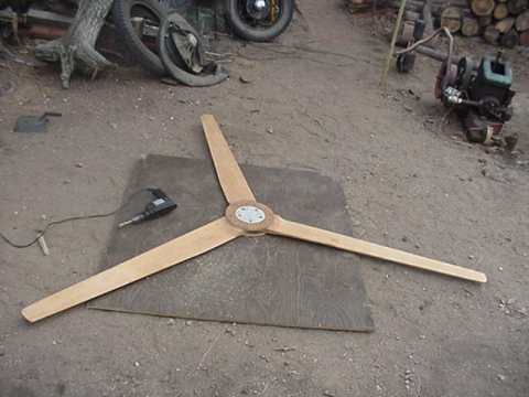
We actually had to make two props for this, since we accidently dropped the machine in our first attempt to raise it! Click here to read about that failure! The first prop we made out of the very best, vertical grain knot free fur. The second prop we made out of some fairly clean Lodgepole pine we had on hand. Both worked well, the 2nd prop actually runs somewhat quieter due to reduced thickness. Otherwise, they are about the same and this page will document only the creation of the 1st one!
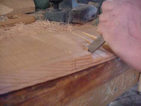
The prop is a 3 blader, 8 feet in diameter. The pitch at the tip is 4 degrees, at the hub it's about 8 degrees. At the hub, each blade is 7" wide, and at the tip they are 3.5" wide. The blades are 7/8" thick at the hub, and 5/8" thick at the tip. The airfoil is of an "intuitive" design, and the thickest part of the prop (the high point of the airfoil) is about 35% of the blades width, from the leading edge. Near the hub, we made relief cuts with a crosscut saw, and chiseled down to the line. After the first 6" away from the hub are chiseled out, it was an easy matter to finish the rest of the prop with a power planer.
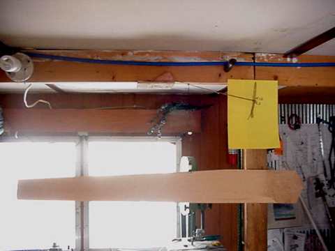
Once the blades were roughed out we had to balance them. The system I usually use (and please...any experts with a better idea let us know!) involves two things. I first find the blades center of gravity (the point at which the blade balances) and then weigh the blade, at that point. We didn't have a scale on hand which was sensitive enough, so we made a simple scale from some bandsaw blade! (show in picture above) I'm not in the habit of adding weights to blades (though I probably should be), but instead we plane material off the blades, untill they all weigh the same and all have the center of gravity located at the same location. It usually goes fairly quickly and I've always had good results with this system. It is true, that when finished some blades might be slightly thicker than others, but if each one is made from fairly similiar wood, which has similiar density, then the blades all turn out very close.
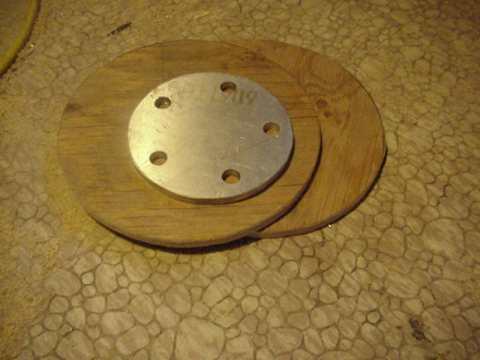
The hub for the prop consists of 2 10" diameter 1/2" thick plywood discs. One of them is routed out, into a ring (6" inner diameter)- so that into it we could inlay a 1/2" thick Aluminium disc, which was drilled out to accept the "studs" by which the prop would be bolted to the alternator. Once all the blades were finished, we coated both plywood discs with epoxy (on the inside) and laminated the discs together with the blades on the inside. The whole sandwitch was tightly screwed together with a bunch of 1.5" wood screws.
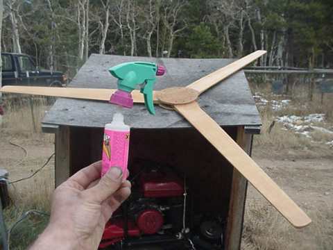
Once the epoxy dried, we finished the prop with "Super Glue" - from a spray bottle. Neat way to put a tough finish on wood, but horribly toxic and very expensive! (about $50!). As it turned out, we smashed this prop and the next prop we simply finished with a thick coat of Linseed oil.
The chassis
It's very simple. About 5' of steel sign post make up the machine. The alternator is welded to the front of it. Even though it is welded on, all the important parts can still be removed, everything except for the wheel spindle, which should never wear out. The alternator's armature (brake disc) is removed easily with one cotter pin and 1 bolt. The stator can be removed by removing 4 bolts/nuts.
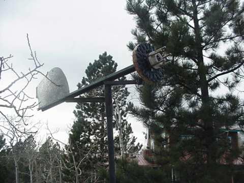
The tail I cut from thin sheet metal, which is bent, and folded over on the back side. Since I have no tin snips, we cut the tail out with an angle grinder. The tail is bolted to the signpost, and 1 heavt steel bracket is bolted to the top of the tail for reinforcement. As it turns out - this is inadequate. I've seen this machine running now for a couple weeks, the tail is NOT longed for the world. It should have been much stronger. We'll take it down soon and fix it.
*** update - since writton, the tail has been replaced twice! 1st one too thin, 2nd one too heavy and large, the new one is smaller and made of plywood which is bolted to the frame ***
A 2.5" diameter pipe, about 20" long serves to mount the machine to the mast....it slips over a 2" pipe. A couple reinforcements are welded between the sign post, the pivot, and the alternator. It's very simple. I has no system of "overspeed" protection. We've made some good windmills up here without it, and many have held up for the long term. I'll be honest, I've seen this machine run in 80+ miles per hour now. Although it held up well, I would be a little more comfortable with some system of high wind protection, not only for the sake of the turbine itself, but also for the tower. I'll definitely look into some system of governing the next time I make a prop 8' or larger. This wind generator also has no slip rings(the commutator/brush assembly which allows power to flow from the wind generator(which pivots) to the mast). I've never made one with slip rings and it's never been a problem! Although slip rings are nice, they add some work to the project and they are not necessary. This machine has a piece of aircraft cable, which is tightly tied to the wind generator frame, and the mast, and allows for the machine to turn about 4 revolutions either way, before the cable gets tight. The power line, is even slightly more slack than this aircraft cable, so the power line can never get pulled tight. I, and my neighbors have built several machines this way. It has never failed, and you'll rarely if ever see the cable tight such that the machine cannot yaw in the wind. It's a lot simpler, and probably less likely to fail that slip rings.
The Test!
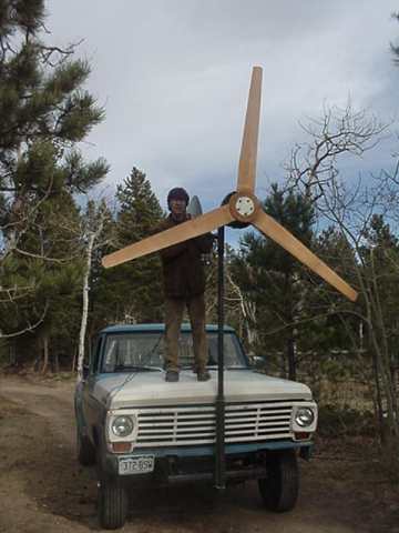
I bolted a piece of the same sign post we used to make the windmill onto the front of my '70 F250, and made some U clamps so that a 2" diameter pipe mast could be fitted. See in the picture above, I am wiring the alternator up for testing. This serves as an excellent test rig. On the passenger floor of the truck is a 12 volt battery, and enough meters on the seat to record whats going on! By watching the meters and my speedometer, and a still day, one can record good information about how the machine performs.
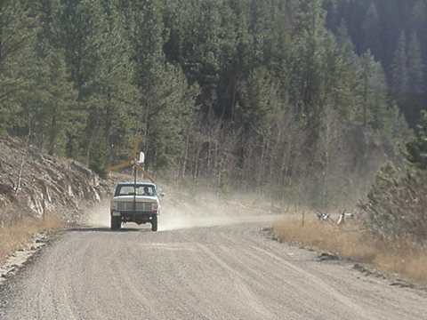
This windmill is a bit hard to start, it takes about 12 miles per hour for a couple seconds to really get it spinning good. When I made the alternator, I soldered the coils together in series in two sets of 9. The two "halves" of the stator could either be hooked in series (for the highest possible voltage) or parallel (for half the voltage and twice the current). When all 18 coils were hooked in series it had difficulty ever charging over 30-35 amps. I realized that there was very little lost (if any) at low windspeeds, and much gained at high windspeeds, to hookup the alternator with the 2 sets of 9 coils hooked in parallel. Again, it didn't start really spinning well untill it saw 12mph for a couple seconds. After that the wind could slow and it would produce around 5 amps @ 10mph, about 20amps @ 20mph, about 35amps @ 30mph, and about 60amps @ 40 mph. At 40 miles per hour, there were wires melting into the seat of my truck and the cab smelt of burning diodes. I've never seen better than 60 out of it, and my guess is that is close to the limit unless some changes were made to the alternator.
The Tower
As stated above, we failed in our first attempt to raise this, which resulted in a broken base, broken prop and a bent mast. In retrospect, it's a good thing we did forget to tighten guy wires, because had we put the mast up in it's origional form, it would have surely failed.
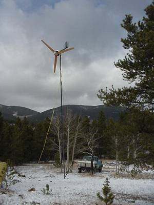
Ward opted for a tower made from steel pipe. It's made up of sections of pipe, which fit tightly together. The bottom 15' is 3" diameter steel pipe, into which another 15' of 2.5" section is slid (About 1' overlap) and into that an 8' section is slid. It fits very tightly and all the joits were welded. At two points on the tower (15' from the base and 30') we welded links of chain around the mast so that the guy wires could be attached. The base was a "Simpson Strong Tie" bracket, which Ward had laid into a fairly large concrete base. At the bottom of the mast, I welded a small pipe, so that the mast was loosely hinged to the base on a 1/2" dia blot. At the bottom of the mast was welded a 2" pipe, 8' long to serve as a jin pole. The jin pole is reinforced with one steel brace at the bottom and a cable which runs up the jin pole 6' and up the mast 15'. Upon raising the mast (1st time) the jin pole immediately started to bend. We got it up a bit, and it stopped bending. We got it allmost all the way up, and it fell to the side, because we had forgotten to tighten the guy wires on one side. The Simpson "strong tie" bracket was torn to pieces, and the top 8' of the mast was bent, and the prop was destroyed.
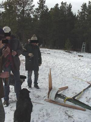
Otherwise, the alternator and everything looked fine. We stayed up late, made a much stronger bracket, and a new prop. Next morning we ground the old bracket out of the concrete, and bolted the new one on using 1/2" bolts and a rock drill so it would be set well in the concrete. It was obvious at that time, that the 2' pipe on the top 8' of the mast was NOT strong enough, it was easy for us to bend it back straigtht - by hand. We cut a piece of 2.5" pipe, 6' long, and slipped it over the existing 2" pipe - making the top section of the tower much stronger, and leaving only enough 2" pipe sticking out for the wind generator to fit on. The jin pole was straighted out and we reinforced it by welding 2 fence posts (which we had on hand) to it. Next time we raised it, we made sure to tighten the guy wire clamps, and things went smoothly with no problems.
Inside the house!
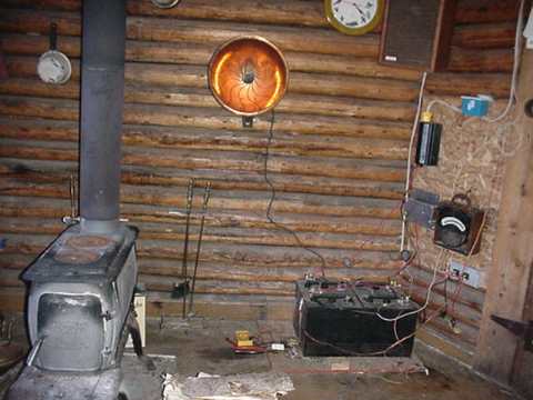
Pictured above is the "inside" part of Wards "utility" sytem. The wood stove heats his whole cabin with no problems. The windmill runs through a couple of bridge rectifiers mounted to a heat sink on the wall. The antique ammeter shows any power coming in from the windmill. When the windmill has the batteries topped off (which doesn't take long), the power is diverted into the antique parabolic space heater, which is bolted to the wall to the right of the heating stove. Although this doesn't make much heat, it does make some on windy nights, and it keeps the windmill from running too fast (at least, that's the idea...).
In Conclusion
The total cost of this installation came in around $500, most of that was for the pipe tower, and the expensive extension cord Ward purchased to bring the power into his house from it. The windgenerator itself cost around $200, including Volvo parts, magnets, glue....everything. Had we used a wooden tower (which I think would've been stronger) and less expensive wire the whole project could've come in around $250-$300. It's a pretty powerful windmill for that price! It does have some problems which I'm sure time will sort out. It would start easier if I'd picked better metal for the laminates, I used bandsaw blade material, and it's hystoreses makes the machine a bit hard to start in low winds. It surely also creates inefficiencies. If this were not the problem that it is, I would be able to decrease the airgap between the armature and the stator greatly, and it's output would be significantly increased. Read more about that in the alternator page. The tail came apart, so a stronger tail than described above is necessary. I've watched it in super high winds and it seems to hold up well otherwise. The tower looks a little rickity in high winds - I'd surely do no less next time, in fact...I'm tempted to further reinforce this tower! Although I believe an 8 foot prop, with no overspeed protection is risky, it's very strong and I believe no overspeed protection is needed. The bearings are more than strong enough and in watching the machine I believe it'll hold up! Only time will tell. If it were any larger, it would need some overspeed protection for sure. Otherwise, I have no complaints. The prop is very quiet, you cannot hear it at all till the machine is producing over 30 amps! I've seen it make 700 watts at 12 volts in high winds. I believe if the alternator were improved, with a better core material and a much smaller air gap, it would be capable of at least 1000 watts at 12 volts, probably much more at 24v. So, soon...I'll try to make one like this with some of these improvements in mind.
Be sure to check out Hugh Piggot's site! He's a pro at making homebrew windmills.... all of the problems I'm having are ones he's solved and his plans are excellent. You'll find some excellent alternator ideas, a good overspeed protection system, lots of info on blade design, and fun reading! Also be sure to check the many resources available on our Links page and feel free to email, or use our discussion board if you have any questions or comments about this stuff!
Update! Jan 2002
This wind turbine has been up and down a couple times now. 1st failure - as you may have seen, we forgot to tighten the guy wires on one side and it fell over breaking the prop. 2nd failure, the tail cracked and blew off! We replaced it with a large (About 25" diameter) old circle saw blade, from an old shingle mill. It ran for a few weeks very nicely, and then in one night of ferocious winds, we woke up to a broken prop, a bent mast, and a missing tail! Not sure exactly what led to what, but - I'm starting to think we should seriously consider some way to shut it down in high winds! Again - the alternator held up fine though. We made a new 8' 6" two bladed prop for it - it's of very strong wood and somewhat thicker near the hub. We also built a new stator for the alternator, replacing the bandsaw blade material with 1/2" wide strips of 22 gage cold rolled sheet metal (which is a LOT better than bandsaw blade!). I rewound the stator with 18 coils of AWG 14 magnet wire, and I doubled up the magnets. (so the magnets are now 1.5" diameter X 3/8" thick). We've yet to raise it - still have to straighten the mast, but we have tested it's performance on the nose of my truck. It does somewhat better, and the prop seems to run a little slower (which is good). Kicks in around 10mph doing 5 amps and quickly rises to around 70 amps at 35 mph! I figure the odds be 50/50 that it will blow up in a high wind once we raise it!
