Testing Homebrew Alternators with Gas Engines

It seems a bit tricky for me to build alternators for wind turbines and get everything right the first time around. Calculating the number of windings to get a good cutin speed is not too hard, but getting the power curve the alternator close to that of the blades is always tricky, and it seems I usually build the alternator such that they are producing a bit too much power at too low an rpm so that the blades stall, and we have to take the machine down and adjust the airgap, or add some resistance to the line between the wind turbine and the batteries. It seems a good idea to do some testing on the ground so perhaps I can get things a bit better matched up before we actually put it up on a tower.
Pictured above is my first attempt. It's an old Fairbanks Morse 'Z' engine, rated 6hp at 400 rpm. You can see the flange I welded to the crank shaft. It fits the 'Volvo' bolt pattern.

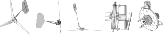
Above Im trying to get some data on one of the brake disk alternators which are intended to run with a 10' diameter prop. Click Here to see a page about identical wind turbines with identical alternators and their construction.
I knew this engine wouldn't be ideal - the rpm varies quite a bit, it's not very smooth because it's a 1 cylinder machine. So, in practice all the readings I got varied quite a bit with each revolution of the engine. I had a scale there and a long lever to it so I could estimate foot pounds and try to come up with some HP figure, but the readings were not smooth enough to get much idea or really use the data. But here is the rough data I got...
At 200 rpm system voltage was at 17, current was 15 amps, and I had about 4 pounds on the scale.
At 225 rpm, voltage was at 17.3, current was 22 amps, I had roughly 5 pounds on the scale.
At 250 rpm, voltage was 17.7, we had 30 amps, and about 6 pounds on the scale.
At 275 rpm we had 18 volts, 45 amps, and about 7 pounds it seemed...
And that was the limit for the engine, I was at full throttle. This alternator is identical to the last few we've made up here, it seems quite a bit too powerful for a 10' prop I think (12 2" X 1/2" disk magnets on each rotor, 9 coils of #12 wire - 35 windings per coil and all the coils wired in star). Although none of this is very scientific and I've not worked out any numbers yet, it's producing more power than a 10' prop could hope for at any given rpm. This is why we've been having to add resistance to the line, or open the airgap on most machines - especially those that have short lines. Had I tested it on the engine with even bigger/better batteries... the problem would seem even worse...
At 175 rpm, with a 10' prop, I think we might see 8 - 10 amps @ 13 volts in a 10mph wind. This alternator is doing at least 12 amps... and the higher the windspeed goes the more the power curve is seperating from that of the prop.
It gave some interesting information though, and it's always fun to have an excuse to put such a wonderful old engine to use! Click Here to see a short movie of all the fun!
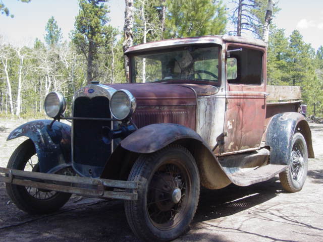
So, I decided I needed a smoother and more powerful engine. Rosy the Truck, a '30 Ford with a 40 HP 200 cubic inch flathead 4 cylender should do nicely.
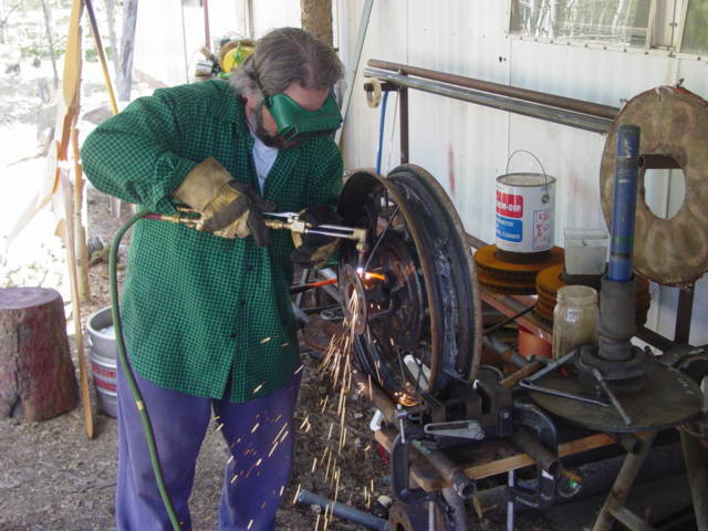
George was up and he helped me do some cutting and welding on an old warped/cracked wheel I had around.
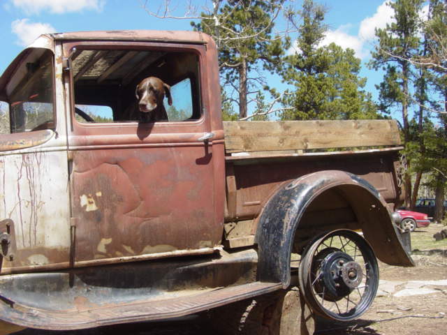
Flash is at the helm, we've got the Model A wheel with the flange that fits the Volvo bolt pattern mounted. It runs pretty well, a little wobble, but not much.
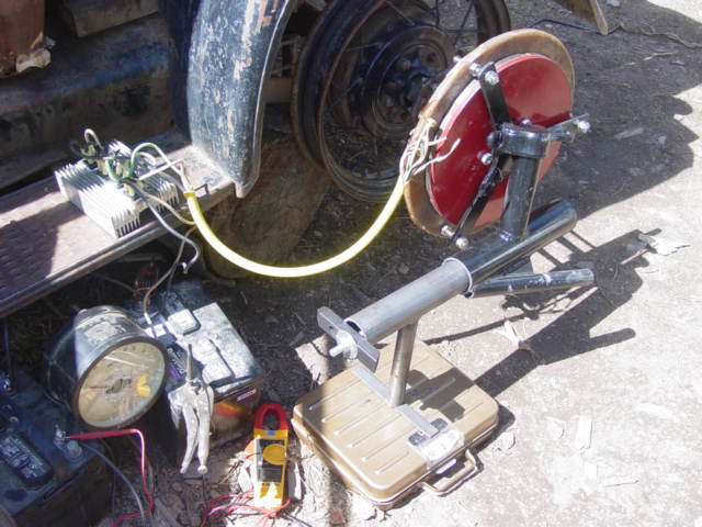
This time I'm testing a larger alternator which is intended for a 15' diameter wind turbine. Click Here to see a page about the these larger machines which are lots of fun! In the picture above we have the alternator bolted to the wheel, and it's hooked to rectifiers and wired to a 24 volt battery bank. (This machine is intended for a 24 volt system). I've got an optical Tachometer, a DC ammeter, an AC voltmeter, and the alternator is held from spinning by a foot which rests on a scale so that I can read Foot Pounds fairly well. It does wobble a bit so at lower rpm I'm unable to get very accurate readings on the scale. Perhaps some sort of shock absorber would help even things out. I also had trouble getting the engine to run slow enough to get much info below about 120 rpm
Lots of fun though! Click Here to see a brief movie of this setup!
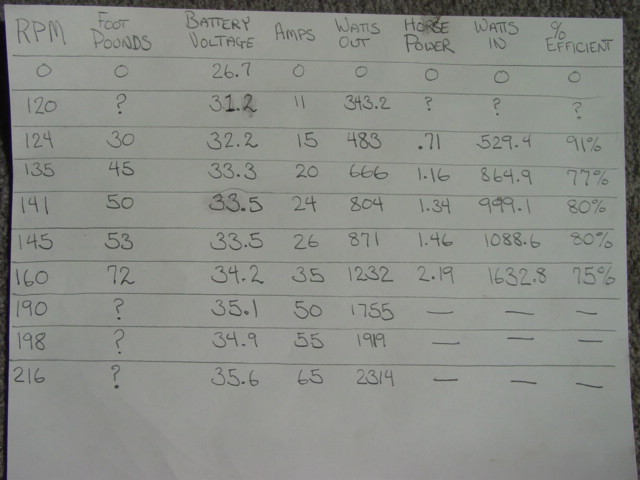
So here's the data I got off it. It's a bit inconsistant, some things don't quite make sense - but that's the real world, this setup still has lots of room for improvement. My scale only goes to 80 pounds, so at higher rpm I couldn't get information regarding foot pounds or efficiency. My guess is that efficiency probably starts dropping off quickly above 2KW. It's intersting though - and probably all the information I need. I think if we had a very short and thick line from the machine to a large battery bank I'd have problems with the blade stalling, but this machine will be quite a ways from the batteries and I have a feeling the alternator will come out close for a 15' prop in this application. Time will tell...
It's intersting to see how hot the stator gets at different current levels. I think I would run this all day at about 20 amps, it warms up a bit, but seems to stabilize. At 40 amps it gets rather hot fairly quickly. Of course, down here on the ground there is no wind going by, and I suspect in the air things might cool down much faster. Again, time will tell... it'll either work fine, or it'll melt!