On this page we attempt to give a brief introduction to the basic concepts of designing and building wind turbines.
| Site | Tower | Anemometers | Generators & Alternators | Cut-In Speed | Alternator Design |
| Rotor Design & Carving | Furling & Shutdown | Regulation | Slip Rings | Futher Reading |
Where do you start???
First, do your homework! Why re-invent the wheel when you can learn from others' successes and failures? There are many useful books, websites and plans available. Check our recommended reading list HERE.First, figure out how big a wind generator you are willing to tackle, either commercial or home-brewed. There is really only one important measure of windmill size...the swept area. That's how many square feet (or meters, if you are into that sort of thing) of area the windmill's blades cover during a rotation. The formula for swept area is Pi r^2, where Pi is 3.1415 and r is the radius of your prop. The available power from the wind increases dramatically with the swept area...but so do the stresses on your blades, tower, bearings, tail. More stress means stronger engineering and materials are required, and a much larger, more complicated and expensive project.
Site
- Location--First, figure out the direction from which the prevailing winds in your area usually come. You can determine this by observation during wind storms, and by looking at the trees near your site. Trees that are all leaning the same direction and that have branches mostly on one side of the trunk are a good indication of prevailing wind speed and direction. Local airports and weather stations can sometimes provide you with this information. The National Renewable Energy Laboratory in Golden, CO publishes an excellent Wind Energy Resource Atlas of the United States on the internet, for free. A Logging anemometer that also records wind direction can be useful here too, though expensive.
- Height: Flying a wind generator close to the ground is like mounting solar panels in the shade! Your wind generator should be located at least 30 feet above any obstruction within 300 feet in any direction-- many sources recommend even more. Short towers in turbulent locations cause drastically reduced power ouput, and extreme physical stresses on the turbine and tower.
- Distance: The distance between your wind generator and your batteries can also be a problem--the closer the better, to avoid losses in long wires and to keep the wire size required down to a reasonable thickness and cost. 12 volt systems are the worst for power transmission losses--you end up needing very thick wire. A 24v or 48v battery bank can save you big money on wire!
Tower
Check out our TOWERS page for some home-brewed solutions that are cheap and easy to fabricate, plus lots of details and pictures. There's also lots of tower information, discussion and pictures available by Searching the Otherpower discussion board for 'towers'.- Your tower must be extremely sturdy, well-anchored, and tall enough to get above obstructions. We've seen 1.5 inch steel pipe bend like a pipe cleaner in 50 mph winds, underneath a wind machine with only an 8-foot rotor. Some wind energy guidelines tell you to plan on spending at LEAST as much on your tower and power wiring as on the wind generator itself!
- Do you like to climb? The two basic kinds of tower are the Tilt-Up and Stationary. A stationary tower is the most sturdy and trouble-free, but you have to climb it to install, maintain or remove the wind machine. A crane is often used for installation, an expensive proposition--though you can do it yourself by climbing the tower and moving a gin pole up it as you add each new section. If climbing towers disagrees with you, go for a tilt-up. Then all maintenence can be performed while standing safely on solid ground.
- Roof mount? We strongly recommend against mounting a wind generator on your roof. The winds near rooftop level are very slow and turbulent, and power output will be drastically reduced. This goes for ALL types of wind turbine, not just ours. Again, your turbine needs to be mounted at least 30 feet above anything within 300 feet in any direction. Vibration is also an issue. Though the manufacturer of the AIR 403 says it works, we have observed first-hand the vibration and noise during a windstorm in two different roof installations...it is VERY noticable and irritating. And keep in mind that the AIR 403 is a very small unit (only a 1.3 meter prop) that makes very little power...a larger mill would be unbearable, and possibly dangerous to your house itself. Most commercial and homemade wind generators don't make much physical noise, but some vibration is unavoidable due to the nature of permanent magnet alternators. Listen to the vibration of Ward's 7 foot diameter windmill (12 second .WAV file, 140K) and hear why we don't recommend roof mounts! Ward's mill is actually very quiet; this audio clip was taken with the microphone pressed against the steel mast to give an idea of the vibration that would be transmitted into your house with a roof mount. The buzzing sound is the vibration of magnets spinning past coils; the clanking is from the sectional tower itself. The windmill rotor itself makes very little noise.
Anemometers
- It is essential to know the real windspeed in any wind generator installation, commercial or homemade. This allows you to see if the machine is performing correctly, and extremely high windspeeds might be a clue that you should shut the mill down for the duration of the storm. If you plan on investing significant money in wind power, a logging anemometer might help you decide if your local wind resource is worth the investment. Commercial anemometers and weather stations are very expensive, but can be found with a quick Google search...you can also try one of the homebrew options below.
- Build your own anemometer: We built an accurate anemometer for under $10 using plastic Easter eggs. See it here! It counts frequency with a simple circuit, and can be adapted to use with computer data acquisition equipment. Another option uses a pre-fabricated cup assembly and a bicycle speedometer, you can see our page about it HERE.
- Logging anemometer kit: This ingenious kit is from Australia and costs less than $100 US, including shipping. It tracks wind speed and direction, and logs data to its own memory, including average and peak readings. And, it interfaces directly to a PC...your wind data can import live right into a spreadsheet! See it here.
Generators and Alternators
- Terms--On our site, we try to use the term Generator to describe a machine that produces Direct Current (DC), and use the term Alternator to describe a machine that produces Alternating Current (AC). However, the term Generator is also used generically to describe any machine that produces electricity when the shaft is spun.
- Options--The alternator or generator is the heart of your wind machine, and it must be both properly sized to match your swept area, and produce the right type and voltage of power to match your application. Unfortunately, there are no commercial or surplus products than can be easily matched to a set of blades for building a wind turbine. It's MUCH more practical to build your own alternator than to try and adapt a commercial unit that was designed for a completely different purpose. If you try that anyway, PM converted induction motors, DC generators, DC brushless PM motors, vehicle alternators, and induction motors are options...but are marginal performers at best. We cover the different types extensively on our Alternator and Generator Comparison page.
- Application--Wind-generated electricity can be used for battery charging and for connection with the power grid. All of our designs and information are about battery charging at this time, since we all live 12 miles from the nearest power line.
- Single Phase vs. Three Phase--3 phase offers some advantages over single phase in most alternators. Most small commercial wind turbines use 3 phase alternators, and then rectify the output to DC (direct current) for charging batteries. When building an alternator from scratch, single phase seems attractive because it is simple and easy to understand. 3 phase is not really any more difficult. For some details, look at some of our later wind turbine experiments vs some of the earlier ones. Going 3 phase allows for squeezing more power from a smaller alternator. It significantly reduces line loss, and it runs with less vibration. Older single phase alternators we made vibrate much more (and make more noise) than 3 phase machines.
- Speed--The shaft speed is a very crucial factor in all types of alternator and generator. The unit needs to make higher voltages at lower rpms, otherwise it is not suited for wind power use. This goes for all power units...even motors used as generators and alternators should be rated for low rpms. This is also why vehicle alternators are not suited for wind power use, see our Alternator and Generator Comparison page for more details.
- Start-Up Speed--This is the windspeed at which the rotor starts turning. It should spin smoothly and easily when you turn it by hand, and keep spinning for a few seconds. Designs that 'cog' from magnetic force or that use gears or pulleys to increase shaft speed will be poor at start up. A good design can start spinning in 5 mph winds and cut in at 7 mph.
- Cut-In Speed--A wind generator does not start pushing power into the battery bank until the generator or alternator voltage gets higher than the battery bank voltage. Higher shaft speed means higher voltage in all generators and alternators, and you want to try and get the highest shaft speed possible in low winds--without sacrificing high-wind performance. Most commercial wind generators cut in at 8-12 mph. The generator's low-speed voltage performance, the design of the rotor (the blades and hub), and the wind behavior all factor into where cut-in will occur.
- Voltage Regulation--With battery-charging windmills, voltage control is not generally needed--until the batteries fill up. Even if your alternator is producing an open-circuit voltage of 90 volts, the battery bank will hold the system voltage down to its own level. Once the betteries are full, you'll need to send the windmill's output to a 'dump load' such as a heating element. This regulation can be done manually by simple turning on an electric heater, stereo, or lights. Automatic systems can be built or purchased too.
- Battery Bank Voltage--In addition to having less line loss, 24v and 48v power systems give other significant advantages in wind alternator systems. The primary consideration for the wind turbine builder or buyer, however, is that the alternator must be wound differently for different system voltages.
- Inefficiency--Every generator has a certain speed at which it runs most efficiently. But since the wind is not constant, we must try to design to a happy medium. As the wind speed rises, the raw power coming into the generator from the wind becomes more than the generator can effectively use, and it gets more and more inefficient. This power is wasted as heat in the stator coils. Alternators with wound fields can adjust the magnetic flux inside to run most efficiently, but PM alternators cannot. An alternator that uses many windings of thin wire will have better low-speed performance than one that uses fewer windings of thicker wire, but higher internal resistance. This means it will become inefficient more quickly when producing higher amperage as wind speeds and power output rise. The formula used to calculate power wasted from inefficiency is AMPS^2 * RESISTANCE = Power wasted as heat in the alternator windings (in watts).
Alternator Design
- Factors--Making PM alternators from scratch is sort of a "black art"--there are many factors that enter in to it, we try to discuss some of them below. And then, you must add in another important factor, the design of the blades. We discuss that below also. We didn't start building windmills and alternators by doing a bunch of math...we just jumped right in, made lots of mistakes, and eventually wound up with a satisfactory design by observing performance and changing one variable at a time. The difficult part is getting the best match between the blades and the alternator.
- Bearings--The operative word here is STRONG. Besides having to withstand vibration and high rotation speed, there is a significant amount of thrust back on the bearings from the wind, and it increases geometrically as the prop size increases. That's why we've moved to using standard trailer wheel bearings in our designs, they are tapered and designed to take the thrust loads. The front bearings in our converted AC induction motors have so far held up well, but they are not designed for that kind of load. DC tape drive motors are especially vulnerable--the front bearing will eventually fail dramatically in high winds if extra bearings are not added.
- Air Gap--This is the distance between the magnets and the laminates in a single magnet rotor design, or between two magnets in a dual magnet rotor design. The smaller the distance, the better the alternator performs. This means it's important to keep the coils as flat as possible, and to make the armature fit very precisely near the stator...if it is not perfectly square, the air gap will be larger on one side of the alternator than the other, and performance will be compromised. Halving the airgap gives 4 times as much magnetic flux.
- Number of Poles--A 'pole' is either the North or South pole of a magnet. Generally when building an alternator we need a seperate magnet for each pole. The faster that alternating north and south magnets poles pass the coils, the more voltage and current are produced. But surface area is important as well. If we have a very narrow magnet (required for using many poles), the field strength would be much weaker over a distance than a wider magnet. So like all things with making wind turbines, there is a compromise to be made. We choose a number of poles that allows for reasonably sized coils and a good strong magnetic field through whatever airgap we wind up with. It must always be an even number. For a 3 phase machine we like 4 poles for every 3 coils, although there are certainly other very feasable options. In most cases, for a 3 phase machine we'd have somewhere between 8 and 16 poles (magnets) unless perhaps the machine were to be very large.
- Series or Parallel? Star or Delta?When coils are connected in series, the voltage increases and so does resistance. When connected in parallel, voltage stays the same but amperage increases and resistance decreases. Also, parallel connections in an alternator can cause current to flow where you don't want it to, called 'parasitic losses.' The correct configuration for your project depends on many factors. Windstuff now's 3-Phase Basics Page has some great diagrams that explain 3-phase, star and delta. We wire all of our alternators in Star.
- Magnets--The stronger, the better. The larger and stronger your magnets are, the more power you can produce in a smaller alternator. Neodymium-Iron-Boron ("rare earth", NdFeB) are by far the strongest permanent magnets known to man, and are ideal for building permanent magnet alterantors. Many older designs call for strong ceramic magnets, this was mainly because of price. We do sell large, high-grade ceramic magnets that are suitable for alternator use, but in practice NdFeB magnets will give over 4 times as much power in the same space than ceramics. Plus, prices on large NdFeB magnets have dropped dramatically since they were first invented in the 1980s. We have a big selection of them at our Online Store, including quantity discounts on sets of large magnets for building alternators. WARNING! Large NdFeB magnets are EXTREMELY powerful, and can cause serious injury.
- Wire--Enameled magnet wire is always used for winding the stator, because the insulation is very thin and heat-resistant. This allows for more turns of wire per coil. It is very difficult to strip, use a razor knife or sandpaper, and be sure to strip each lead thoroughly! Choosing the gauge of wire is yet another trade off--thinner gauge wire allows for more turns per coil and thus better voltage for low-speed cut-in, but using longer, thinner wire gives higher resistance and therefore the unit becomes inefficient faster at high speeds.
- Magnetic Circuit--Picture a magnet to be almost like a battery. The lines of force from a magnet are said to originate at one pole and return to the other, just like a battery. Air is a poor conductor, both for electricity and for magnetic lines of force. In order to make best use of a magnet (and our copper wire) in an alternator, we need to have the strongest possible magnetic field. Just like copper is a good conductor of electricity, steel is a good conductor of magnetic fields. A good magnetic circuit involves steel between the poles with a gap (the airgap) where we need to utilize the field. In an alternator, our wires should occupy the airgap, it should be no wider than necessary, and every other part of the magnetic circuit should be of steel. We can either use steel laminates (laminated steel reduces eddy currents) or we can have magnets on each side of the coil(s) moving together with steel behind them. Again, look at our various wind turbine experiments to see. It should be said that some of them, like the wooden alternator and the all wooden windmill have very poor magnetic circuits.
Rotor
- A wind generator gets its power from slowing down the wind. The blades slow it down, and the alternator collects the power. BOTH must be correctly designed to work together and do this efficiently. We are not experts at blade design...we sort of started in the middle with a functioning design, and made changes from there. Really, you could make a simple set of blades with a straight 5 degree pitch down the entire length and they would work JUST FINE! But to really tune in the performance of your wind generator, it's important to pay attention to a few factors. ALSO--please forgive us when we slip up and refer to the rotor as a "prop" or "propellor"--it doesn't propel anything! Rotor is the proper term, not to be confused with the rotor of an armature. But we slip up sometimes...
- Blade Material--Wood is really an ideal material for blades. It is very strong for its weight, easy to carve, inexpensive, and is resistant to fatigue cracking. Choose the best, straightest, most knot-free lumber you can find; pine and spruce are excellent. Hardwoods are generally too heavy. Steel and aluminum blades are much too heavy and prone to fatigue cracking; sheet metal would be a poor choice, and extremely dangerous...check out the photo of fatigue cracks on a sheet metal windmill TAIL in Ward's Prop Gallery and imagine what the vibration would do to sheet metal blades! Cast reinforced Fiberglas® blades are very strong, and are common on commercial windmills--but the moldmaking process would take longer than carving a complete set of blades from wood, and there would be little or no gain in strength.
- Diameter--Blades that are too short attached to a large alternator will not be able to get it moving fast enough to make good power. Blades that are too large for a small alternator will overpower and burn it up, or overspeed to the point of destruction in high winds--there's not enough of an alternator available to collect the energy coming in from the wind.
- Number of Blades--The ideal wind generator has an infinite number of infinitely thin blades. In the real world, more blades give more torque, but slower speed, and most alternators need fairly good speed to cut in. 2 bladed designs are very fast (and therefore perform very well) and easy to build, but can suffer from a chattering phenomenon while yawing due to imbalanced forces on the blades. 3 bladed designs are very common and are usually a very good choice, but are harder to build than 2-bladed designs. Going to more than 3 blades results in many complications, such as material strength problems with very thin blades. Even one-bladed designs with a counterweight are possible.
- Tip Speed Ratio (TSR)--This number defines how much faster than the windspeed the tips of your blades are designed to travel. Your blades will perform best at this speed, but will actually work well over a range of speeds. The ideal tip speed ratio depends on rotor diameter, blade width, blade pitch, RPM needed by the alternator, and wind speed. Higher TSRs are better for alternators and generators that require high rpms--but the windspeed characteristics at your particular site will make a big difference also. If in doubt, start in the middle and change your blade design depending on measured performance.
- Taper--Generally, wind generator blades are wider at the base and narrower at the tips, since the area swept by the inner portion of blades is relatively small. The taper also adds strength to the blade root where stress is highest, gives an added boost in startup from the wider root, and is slightly more efficient. The ideal taper can be calculated, and it varies depending on the number of blades and the tip speed ratio desired. Hugh Piggott's Windpower Workshop book and his free Blade Design Notes contain the relevant formulas. Honestly, though...if you simply take a look at a picture of a functioning small-scale wind generator's blades and estimate the taper by the eyeball method, you will come very close to meeting the criteria and have a very functional blade. Our Basic Blades page gives a basic introduction to blade design and carving.
- Pitch and Twist--As we've said before, a simple wind generator blade with a straight 5 degree pitch down the whole length would give adequate performance. There are advantages to having a twist, though--like with taper, having more pitch at the blade root improves startup and efficiency, and less pitch at the tips improves high-speed performance. The wind hits different parts of the moving blade 's leading edge at different angles, hence designing in some twist. One of our common blade designs that's right in the middle for design parameters is to build an even twist of 10 degrees at the root and 5 degrees at the tip--but the ideal solution will also depend on your alternator cut-in speed, efficiency and local wind patterns.
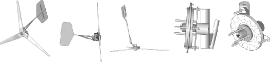
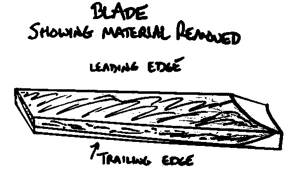
- Carving--Our layout and carving process is very simple...after marking the cut depth at the trailing edge at both the root and tip, the two depths are connected with a pencil line. DanF likes to use a hand saw to make layout cuts into the blade every couple inches along the length before firing up the electric planer...when the saw kerfs disappear, the pitch is correct. DanB prefers to hack into it with a planer right from the start. In case you are fuzzy about how this all goes together, the drawings below might help.
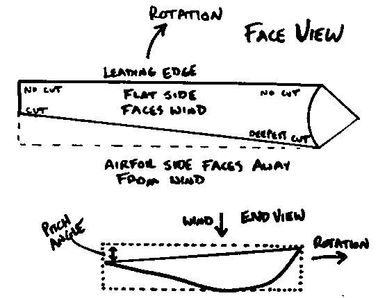
- Airfoil--There are great lengths that you can go to for designing an airfoil...NASA has some great information and calculations out there on the net. But all an airfoil needs to do is maximize lift and minimize drag. You will do fine if you do like we did--find a likely looking airfoil cross section from a working wind generator blade, and copy it. A power planer makes quick work of carving it, and a drawknife is great for carving too, especially with the deep cuts near the blade root.
- Balancing--The blades must be very well balanced to prevent vibration. This is more easily accomplished with a 2-blade rotor than a 3 bladed one. But generally, we simply use a homemade spring scale to make sure that each blade weighs exactly the same, and that each has the same center of balance. A simple balancing jig for any rotor configuration can be made with an upright spike that sticks into a dimple punched at the exact center of the hub. Excess material from the heavy areas can be removed quickly with a power planer. You'll also need to balance the blade in place on the alternator. It's weight distribution can be adjusted by attaching lead strips to the blade root.
Furling and Shutdown Systems
- Furling Systems--We use the term "furling system" to describe a mechanism that turns the wind generator rotor at an angle out of the wind, either horizontally or vertically, to protect the machine from damage during high winds. Ideally it will keep power output levels near the maximum even when fully furled. Our early wind turbine designs didn't use furling systems, and we feel fortunate that some of them are still flying. A wind turbine that furls is also much more gentle on your tower and guy wires--the force on an overspeeding wind turbine increases as the wind gets stringer..
There are a variety of furling system designs: -
- Variable Pitch-- An ideal but extremely complicated solution is to use blades which change pitch depending on the wind speed....these also have the advantage of keeping power output at the most efficient point for the current windspeed. During low winds, the blades are pitched for best startup. In higher winds, they rotate and adjust shaft speed to the ideal RPMs for the generator. In extreme winds, they turn the blades even further to protect the unit from damage. The problem is the complexity of making a system work reliably...but it can be done! Large commercial wind generators use this system exclusively, as do antique and modern Jacobs turbines, and some old WinChargers.
- Tilt-Back--In these designs, the generator body is hinged just behind the nacelle. When wind speed gets too high, the entire nacelle, hub and blade assembly tilts back out of the wind to nearly vertical. As the wind slows down, it returns to normal horizontal operating position by either springs, wind action on a tilted tail, or a counterweight. Commerical wind generators that use this method are the old Whisper models (from before the buyout), the Windstream, and many homemade designs.
- Furling Tail--The generator is mounted off-center horizontallly from the yaw bearing. The tail is also angled in this axis. The tail is also angled in the vertical axis, and hinged. When the wind force back on the rotor is strong enough to overcome the off-axis generator making it want to yaw and the angled tail trying to keep it from yawing, the tail folds up and turns the alternator away from the wind direction, forcing the wind turbine to yaw out of the wind. When wind speeds drops, the tail is returned to normal operating position by gravity, or springs. Many commercial and homemade designs (including ours) use this system, and it has proven to be very reliable.
- Folding Vane--Similar to the furling tail, but the tail boom is fixed, with a hinged vane underneath. Used on some older Winchargers and homemade designs, the disadvantage is that tail and vane are more highly stressed from wind force during furling, as they still are sticking out there in the gale.
- Flexible Blades--The theory is that the blades flex both back toward the tower and around their main axis, and therefore protect themselves from overspeeding. It does work if the materials and details are correct...for example, the blades must not flex back far enough to hit the pole, and they must withstand flexing during cold weather too. The popular Air 403 and new Air X from SouthWest Windpower use this system for furling. One problem is that it is noisy....in fact the Air 403 is noisy even in gentle 15 mph winds, BEFORE it starts producing power. The Air X has some fancy electronic circuitry to reduce noise.
- Air Brakes--Noisy and full of vibration, but they do work. Older WinChargers used this system. Metal cups extend from the hub from centripetal force during high winds, and noisily slow the machine down; they retract back into the hub when the wind slows.
- Shutdown Systems--This is a manual control that completely shuts the wind generator down. It is not allowed to spin at all, and should be able to survive extremely violent winds in this condition. It can be electrical or mechanical.
-
- Electrical Shutdown--With permanent magnet alternator machines, simply shorting the main AC power output leads together should effectively shut down the wind turbine. The problem is that when the machine is spinning at high RPMs during a windstorm, the shutdown may be either impossible electrically (the turbine is performing too inefficiently for shorting the output to have any effect), or too damaging to the alternator (the heat produced in the stator coils by shutdown at high speeds turns the coils into molten slag.) Our normal method is to simply wait for a space between high wind gusts to short the mill with a switch. We have successfully shut down Ward's turbine while it was putting 30 amps into 12vdc...numerous shutdowns at 10-20 amps of output have caused no vibration or problems. You can use a manual switch, or simply a shorting plug to do this. Our homebrew deisgns have never had problems with refusing to stop in high winds when shorted.
- Mechanical Shutdown--These systems physically brake the wind generator, or force it out of the wind by turning the tail parallel to the blades. Even the mighty Bergey Excel 10kW wind turbine has a mechanical crank for emergency shutdown. Generally, a cable is attached to a hinged tail, with a small hand winch located at the bottom of the tower for the operator.
Regulation
- With battery-charging wind generators, regulation of the incoming voltage is accomplished by the battery bank itself, until it is fully charged. Though a PM alternator or DC generator's open-circuit voltage might be 100 volts, the battery bank keeps the wind generator circuit voltage at its own level. Once the battery bank fills, system voltage will rise rapidly and something must be done with the uneeded incoming power. Simply disconnecting the windmill is not an option--a windmill allowed to 'freewheel' will quickly blow itself up from overspeed. The power must be diverted into some sort of load.
- Turn on Some Lights! --This is the oldest, simplest and most reliable method of regulation. Problem is, you have to be there to do it. But by turning on house lights, heaters, etc. that more or less equal the extra power coming in, you prevent the batteries from overcharging, keep a load on the windmill and keep your system voltage in the normal range.
- Shunt Regulation--These systems simply sense the battery voltage and divert power directly from the batteries into heating elements (known as a 'dump load'), thus keeping a load on the windmill while avoiding overcharging of the batteries. The very simplest solution is a manually thrown switch that disconnects the incoming power from the batteries and connects it to some heating elements...just keep in mind the voltage requirements of the heaters must be a good match to the alternator for braking to occur. Simple systems that divert all the incoming power at once can be built using Trace C-series charge controllers or relays and voltage sensors. More complicated systems use power transistors or pulse width modulation to divert only part of the incoming power, or the entire amount, as charging needs require. Both Home Power Magazine and Hugh Piggott's Website have plans and schematics for building shunt regulators. Some commercial solar charge controllers can be set to function as dump load controllers, like the Trace C40. A controller intended only for solar power will NOT function with a wind turbine, nor will an automotive voltage regulator.
- Diodes--A permanent magnet DC generator (such as a surplus tape drive motor) does need a diode in the line--otherwise, the battery bank will simply spin it as a motor. The diode should be rated for higher amperage than the maximum output of the motor, and must be well heat-sinked.
- Bridge Rectifiers--Since alternators make AC power and batteries need to charge with DC power, conversion is needed. This is accomplished with bridge rectifiers, which are simply an array of diodes. For single-phase alternators, standard bridges with 4 diodes are used. The biggest bridge that's commonly available at a reasonable cost is 35 amps--for larger wind generators multiple 35 amp bridges can be hooked in parallel to give greater power handling capacity. The bridges must be well heat-sinked to a large piece of finned aluminum or steel. We sell these rectifiers at our Online Store.
Slip Rings
The power produced by the generator must be transferred down the tower to your power system. Since the actual wind generator must yaw to keep pointed into the wind, the main power wires must be able to handle this. There are 2 options...- Pendant Cable--Our personal experience up here in Colorado is that it is much easier to simply use a length of flexible cable and a steel safety cable instead of slip rings. Use the highest quality stranded, flexible cable you can find and attach it in a loose loop from the wind generator power terminals to where your feed wire comes up the pole. Use a length of wire that allows about 3 or 4 wraps around the pole. Or, run the wire down the center of the tower pipe and let it twist inside. Our experience is that while the cord can eventually wind itself around the pole, it will also eventually unwind itself. Some of our models have flown for years with this kind of system and required no maintenance. With a properly designed wind turbine and furling system, you should hardly ever see the mill make a 360 degree yaw. We simple use a power plug and socket at the bottom of the tower and unplug it once or twice a year to untwist the wire. We've seen commercial turbines on 120 foot towers that successfully use the pendant cable system.
- Make or Convert Slip Rings--Slip rings can be salvaged from old car alternators and converted to wind generator use, or built from scratch using copper pipe, PVC pipe and graphite brushes. Home Power Magazine has had articles in the past about both methods. We have never felt the need to use them and they make for another potential failure point, so we have not experimented with it.
Recommended reading list for your 'homework':
- DanF's series on Small Wind Turbine Basics, published in the Energy Self Sufficiency Newsletter:
- Part 1 -- How wind turbines work, power available in the wind, swept area, average wind speed and what it really means. The basic essentials!
- Part 2 -- High wind survival mechanisms, wind turbine types, drag vs. lift machines, HAWTs vs. VAWTs, tip speed ratio, blade design, and lots of cool pictures and diagrams.
- Part 3 -- Choosing a site, good and bad site examples, anemometers, tower types, lightning protection, power regulaton, birds and bats.
- Our article The Bottom Line About Wind Turbines is an essential introduction to wind power. It covers the basics of how wind comes to us, how much power different size wind turbines can make in different wind regimes, and has a very handy section on detecting wind turbine scams.
- Otherpower.com's Wind Turbine User's Manual should also be considered essential reading, especially BEFORE you take the plunge and buy or build a wind turbine. It will fill you in on exactly what you are getting yourself into with wind power, including towers, installation, controllers, and troubleshooting. It can be downloaded for free from that page, and is available in printed form through our Online Store.
- Wind power information from homebrew wind power guru Hugh Piggott's website. We've learned a BUNCH from Hugh.
- Hugh Piggott's book Windpower Workshop is an indispensable reference for anyone that's thinking about building a wind turbine. His Axial Flux Alternator Windmill Plans are very detailed and highly recommended.
- Homebrew wind power infomation from Ed Lenz's Windstuffnow.com, a highly informative website.
- Read the Renewable energy FAQs on the Otherpower discussion board, and Search the Otherpower.com discussion board. It's highly active and populated by windpower experts and hobbyists worldwide. If you still can't find and answer, by all means please join the board and ask your question there!
- Join the AWEA mailing list for more discussion with wind power experts worldwide.
- Explore other wind power websites from worldwide on our Links page.
Wind Turbine Seminars and Renewable Energy Fairs These can be a very valuable resource for learning about all facets of renewable energy! You'll be able to learn from and network with experts and other interested folks.
- Guemes Island 2004--How to Build a Wind Turbine -- Our pages with details and photos about the excellent seminar we attended--our second time attending. Hosted by Hugh Piggott and put on by Solar Energy International (SEI), these seminars are extremely valuable learning experiences, and loads of fun besides!
- DanF's notes on the 2004 Guemes Seminar -- More pictures, and details of the various design and construction improvements made in 2004, plus some interesting new testing methods.
- Guemes Island 2003 -- How to Build a Wind Turbine -- Hugh Piggott's webpage about the 2003 SEI seminar. Great pictures!
- Rocky Mountain Sustainable Living Fair 2004 -- We put on a seminar, and with the help of our students built a wind turbine in a single weekend.
- Rocky Mountain Sustainable Living Fair 2005 -- A page about the same workshop in 2005. The students built a very nice machine over the course of two days.
- MREA 2006, 6-day workshop --The MREA (midwest renewable energy association.) asked us to give a 6 day workshop at Mick Sagrillos shop in WI... it was lots of fun! We built 3 different sized machines over 6 days... check out DanF's page about it.