This chapter will describe how we build the 'frame' for the wind turbine. This involves a fair bit of metal work. To do this you'll need to have the ability to cut/grind and weld steel. If you're new to this type of work it might pay to practice your skills on some scraps. The tolerances with this are not terribly, again - the design is very forgiving. But some of the welds are critical so you need to be a bit careful. Also keep in mind the dangers of metal work. This is the most dangerous work you'll do to build the wind turbine. Metal is often sharp when you cut it. Grinding can be fairly dangerous - lots of shards flying around and I've seen grind stones explode before, so be sure to wear a face shield. Cutting with a torch or welding has it's obvious hazards (molten hot steel and sparks flying). Just follow proper safety proceedures and odds are you'll live through it.
Materials List
1/4" thick steel plate, 15" square (stator bracket, tail bracket, disk to support the back of the spindle)
1" sched 40 pipe, 6' long (tail boom, tail pivot)
1.25" sched 40 pipe, 9" long (tail bearing)
2" sched 40 pipe, 4" long (to attach alternator to yaw bearing)
2.5" sched 40 pipe, 12" long (yaw bearing) 3" sched 40 pipe, 3.625" long (pipe to support wheel spindle and stator bracket) 1.25" x 1/4" bar stock, 5' 6" long (tail boom gusset, tail vane bracket)
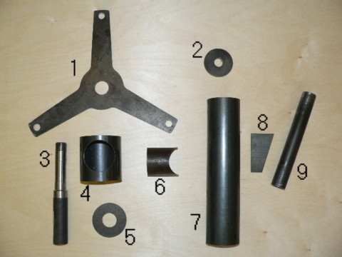
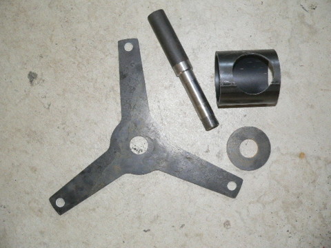
Pictured above are all the parts you'll need to make (or have made) before you start. Not pictured above are the parts of the tail itself which we can discuss later, because it is a seperate part.
1 - Stator bracket. The stator bracket is cut from 1/4" thick steel plate. It serves to support the front of the wheel spindle (on which the main wheel hub/bearings go) and it supports the stator. To lay it out, find center and draw two circles. The inner circle is 4" diameter, the outer circle is 15" diameter. Lay out 3 'spokes' 120 deg apart. The spokes are 1.5" wide at the outer diameter and 2" wide where they meet the inner 4" dia circle. Centered on each spoke at 13.75" diameter is a 1/2" hole (these accept the studs that will mount the stator). In the center of the bracket is a 1.25" diameter hole. This fits the wheel spindle. You can cut this out with a torch, or a plasma cutter easily. If those tools are not available, you can simplify the design keeping in mind that the critical measurements are the locations of the 1/2" and 1.25" holes. Some folks will make the inside 4" dia circle with a hole saw and then make the spokes with bar stock. While it doesn't look quite as neat, it works just as well. The spokes should be fairly rigid so if you do use bar stock use at least 1.5" x 1/4", any thinner might bend under the torque that the stator will impose upon it.
2 - Yaw bearing cap. The yaw bearing cap is simply a disk of 1/4" steel with a 3/4" dia hole drilled in its center. It will be welded to the top of the yaw bearing and the hole will accept the cord from the alternator which will run down the center of the tower. When making the magnet rotors you cut a 2.75" diameter hole in their center. Use the scrap from one of the magnet rotors for this - it's the perfect diameter, all you need to do is drill the hole in the center.
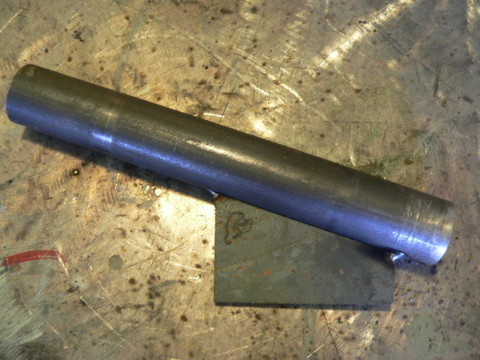
3 - Spindle, part #BT-88. This is the spindle that our wheel hub (Dexter part #81-9A) fits. It's probably the most common spindle in use for 1000 pound trailer axels and it's widely available. There are other slightly cheaper spindle/hub setups but I prefer this one. It's the best choice because it's widely availabe and it's machined on both sides which makes life much easier for us. You can certainly modify the design to accept other brands of spindle/hub assemblies but I think it's easier to stick with the Dexter parts here. Check out the appendix for suppliers.
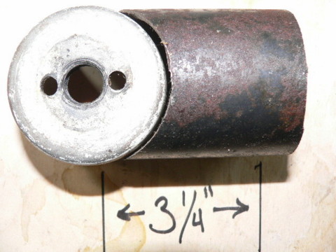
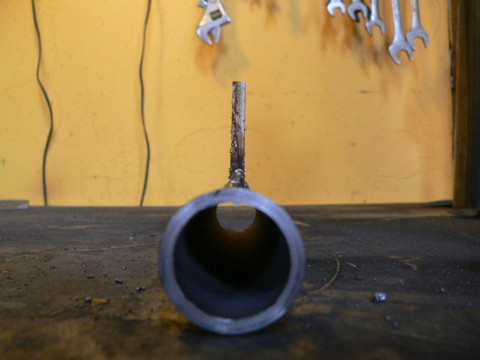
4 - This is the 3" dia sched 40 pipe that supports all the parts of the alternator. It's 3.625" long and we cut a 2.5" hole in it with a hole saw.
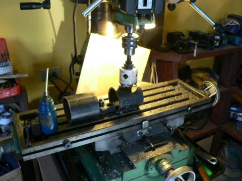
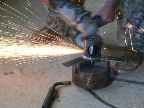
The hole can be cut on center, but I prefer to cut it slightly off center. Cutting it towards one side allows us to push the whole alternator foward in relation to the yaw bearing slightly and gives us a bit more clearance between the stator bracket and the yaw bearing. It also gives us slightly more clearance between the blades and the tower. Use a good high quality bi-metal hole saw. Be sure to run the drill press at it's lowest possible speed and use plenty of cutting oil.
5 - Rear spindle support. This disk is just under 3" in diameter (cut it out with a torch, or a 3" hole saw) and it has a 1.25" diameter hole in the center which fits around the back of the wheel spindle. The stator bracket supports the spindle in the front, this disk supports it in the rear.
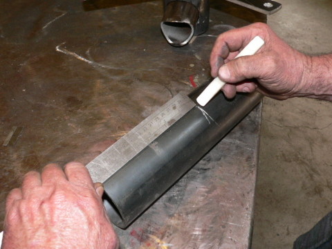
6 - Connects alternator to yaw bearing. This is cut from 2" diameter pipe. One end is coped with a hole saw so that it can be welded to the yaw bearing, the other end is left flat, and fits into the 3" pipe which has a 2.5" hole cut to accept it (part #4).
When we cope this part with a hole saw the distance from the center of the hole saw to the other end of the part should be 3.25". We usually use a 2.5" diameter hole saw to cope this, and then we need to touch it up a bit with a grinder so that it fits nicely against the yaw bearing.
7 - Yaw Bearing. This is the part that slips over the tower top. It's 12" long, made from 2.5" sched. 40 pipe. This is the part that will fit over the tower top.
8 - Tail bracket. This will sit between the yaw bearing and the tail pivot (the pipe that the tail will hang, and pivit on when the machine furls). It's also cut from 1/4" steel plate. It's 3.5" tall, 1" wide at the bottom and 2.125" wide at the top.
9 - Tail pivot. This gets attached to the tail bracket and the tail will slip over it and 'hang' on this part. In high winds, the tail will pivot on this pipe.
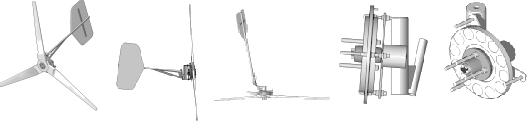
Once all the pieces are cut out you begin welding the machine together. The first step is to build the part that supports the alternator. Once that's finished you attach the tail bracket to the tail pivot, and then you weld both those parts to the yaw bearing.
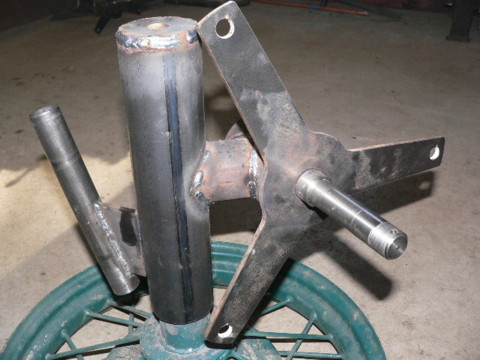
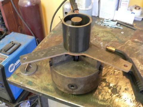
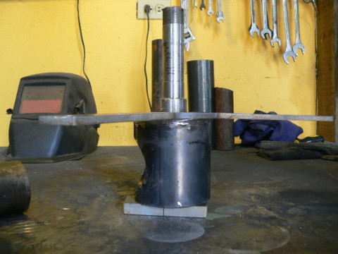
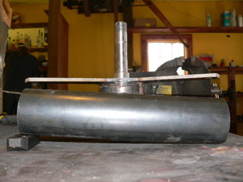
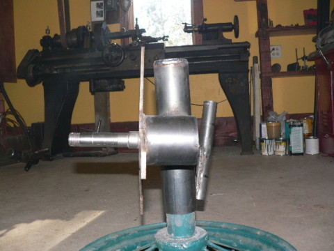
Start by gathering the [parts pictured, the wheel spindle, the stator bracket, the 3" dia pipe with the hole in its side and the 3" disk with the 1.25" hole in its center.
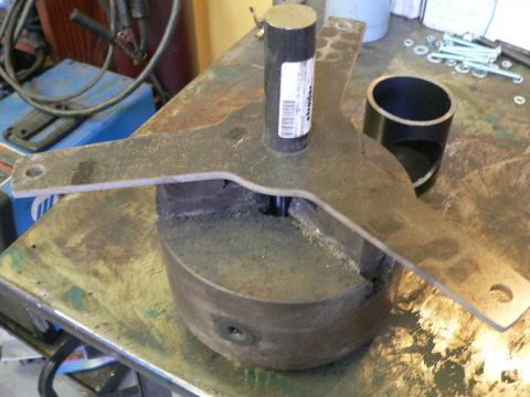
I like to use an old 3 jaw lathe chuck for this, but if that's unavailable a decent sized vice should work fine. You need to clamp the wheel spindle so that the machined part is facing down, and put the stator bracket around it as shown in the picture. 6.625" of the wheel spindle should be sticking up from the surface of the stator bracket. The stator bracket may not be perfectly flat but get things as close to square as possible (so that the angle between the stator bracket and the spindle is always 90 degrees). Tack weld the spindle to the stator bracket in 3 or 4 small spots on different sides. This will hold it in position nicely so that you can really weld it there. If you don't tack weld it first and just start welding around the circle it will be pulled out of square as your welding because weld's shrink as they cool.
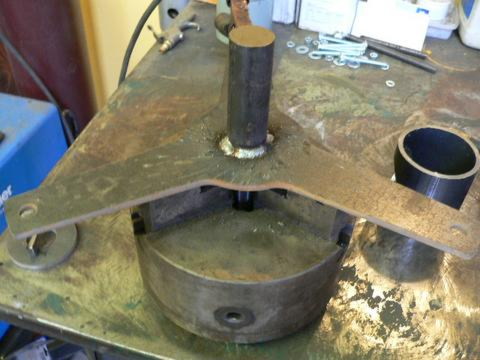
After you've tack welded the spindle to the stator bracket go ahead and weld it there.
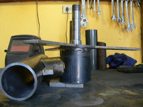
Now center the 3" pipe on the stator bracket. The height of the spindle should be the same as that of the pipe. The 3" pipe has the 2.5" diameter hole you cut in one side. If you cut the hole off center (more towards one side then the other) then put the pipe on the stator bracket so that the hole is most distant from the stator bracket. If you cut the hole on center it obviously doesn't matter. Where the 2.5" diameter hole points with regard to the spokes on the stator bracket is not terribly important, but we usually like to put it opposite one of the spokes. This way when the wind turbine is together, we'll have 1 of the spokes coming out from the stator bracket pointing exactly away from the yaw bearing... it just looks a bit neater I think and it makes the machine less fragile if we have to ship it somewhere, but it doesn't affect the workability of the wind turbine. Don't weld the 3" pipe to the stator bracket yet...
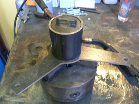
Now take the 3" diameter disk with the 1.25" hole in it, and position it inside the 3" pipe. It should fit around the back of the wheel spindle and inside the 3" pipe as shown in the picture. A magnet serves nicely to hold it there before you tack weld it.
Once everything looks good and centered go ahead and tack weld everything together. (3" pipe tack welded to stator bracket, 3" disk tack welded to 3" pipe and wheel spindle)
Then weld it all together for good as shown in the picture.
It's not necessary but it'll look much nicer if you take the time to grind your welds down and smooth things out. Now is the time for this, once we weld this part to the yaw bearing you'll not be able to get at some of the welds very well with a grinder.
Now we'll weld the assembly that we just finised to the yaw bearing. There are a couple of weird angles involved here and the distance between the yaw bearing and the wheel spindle is fairly critical. We've built a jig to make assembly of a wind turbine quite easy and if you plan on building more than one machine such a jig may pay off. But it's fairly easy to do without one. Start by putting the spindle/stator bracket assembly that you just finished on top of a 1/2" thick shim (a piece of wood or 1/2" thick steel or whatever...).
The yaw bearing is 12" long. Mark the center of it at 6".
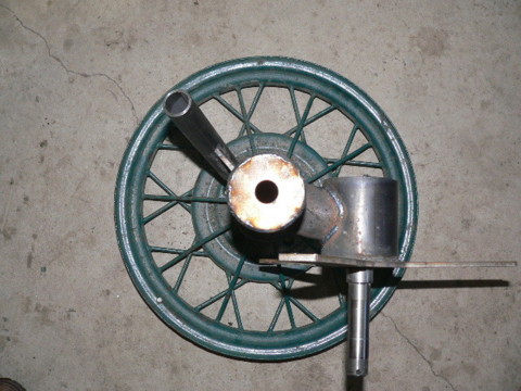
Pictured above is the layout and were looking at it from the bottom of the wind turbine. You can see how the 1/2" shim under the spindle/stator bracket assembly pushes the alternator foward a bit. If you can imagine a vertical line through the center of the yaw bearing (the 12" x 2.5" pipe) parallel to the spindle, there should be 5" between it and the center of the spindle. In other words... when we're finished the center of the alternator will be 5" to one side from the center of the tower.
Looking at the same thing from the side. We've put a 3/4" shim under the top of the yaw bearing. When finished, this will cause the alternator to be tipped back about 5 degress so that the wind turbine blades are tipped back and have nice safe clearance between their tips and the tower.
Tack weld this all together. Inspect it to make sure the offset between the spindle and the yaw bearing is correct, and that all the angles are correct. If all looks good then weld it together.
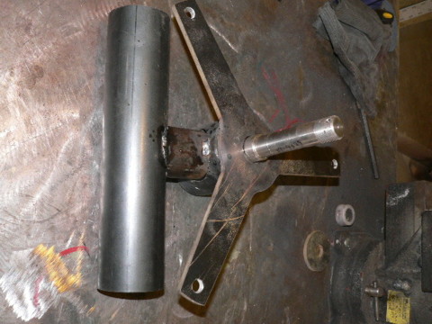
Get the tail pivot bracket and the tail pivot (parts 8 and 9 as shown in the previous picture). Mark the center of the tail pivot (4.5") and position the bracket so that it's top (the 2.125" wide part) is at the half way mark on the tail pivot. Tack weld it at the top and bottom and then quickly on each side as shown in the picture above.
Looking down at it from the top it should look like the picture. If everything looks right, then weld it. This needs to be a good weld with good penetration because the tail hangs on this part.
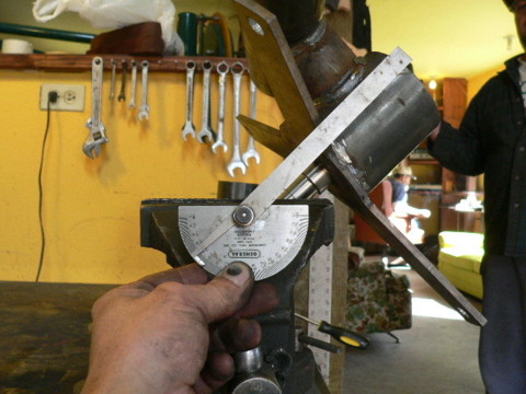
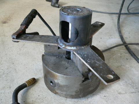
Take the main part of the wind turbine and put it in a vice so that it's tipped at 45 degrees as shown in the picture.
Put the tail bracket and pivot on top so that it's pointing straight up, and tack weld it there. Again, inspect it - make sure everything is straight and square and if it's all good then weld it there. This is probably the most critical weld on the machine. The tail can slam around on the tail pivot in high winds and all this weld takes all the abuse. This needs to be a high quality weld with good penetration or you risk having the tail fall off which can be disastrous especially if it hits the blades. We've never had this happen but I always worry about it. If you weld this well there should be no problem.
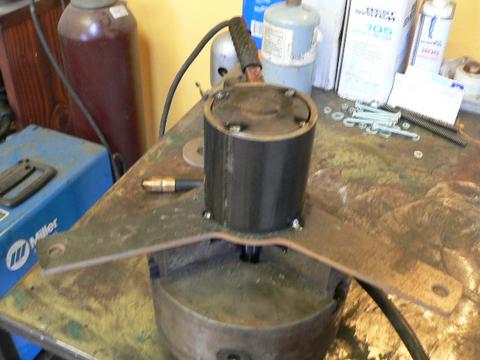
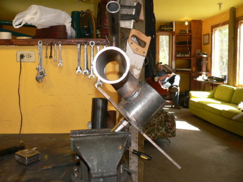
Now you can weld the yaw bearing cap to the top of the yaw bearing as shown in the picture.
Pictured above is how your machine should look from the top.
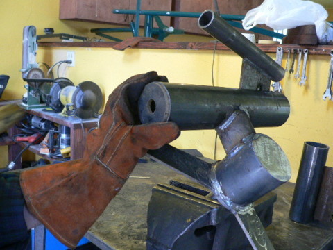
Shown in the picture above is the same machine veiwed from the side. All thats left is to build the tail.
Click Here to return to the front page of this project.